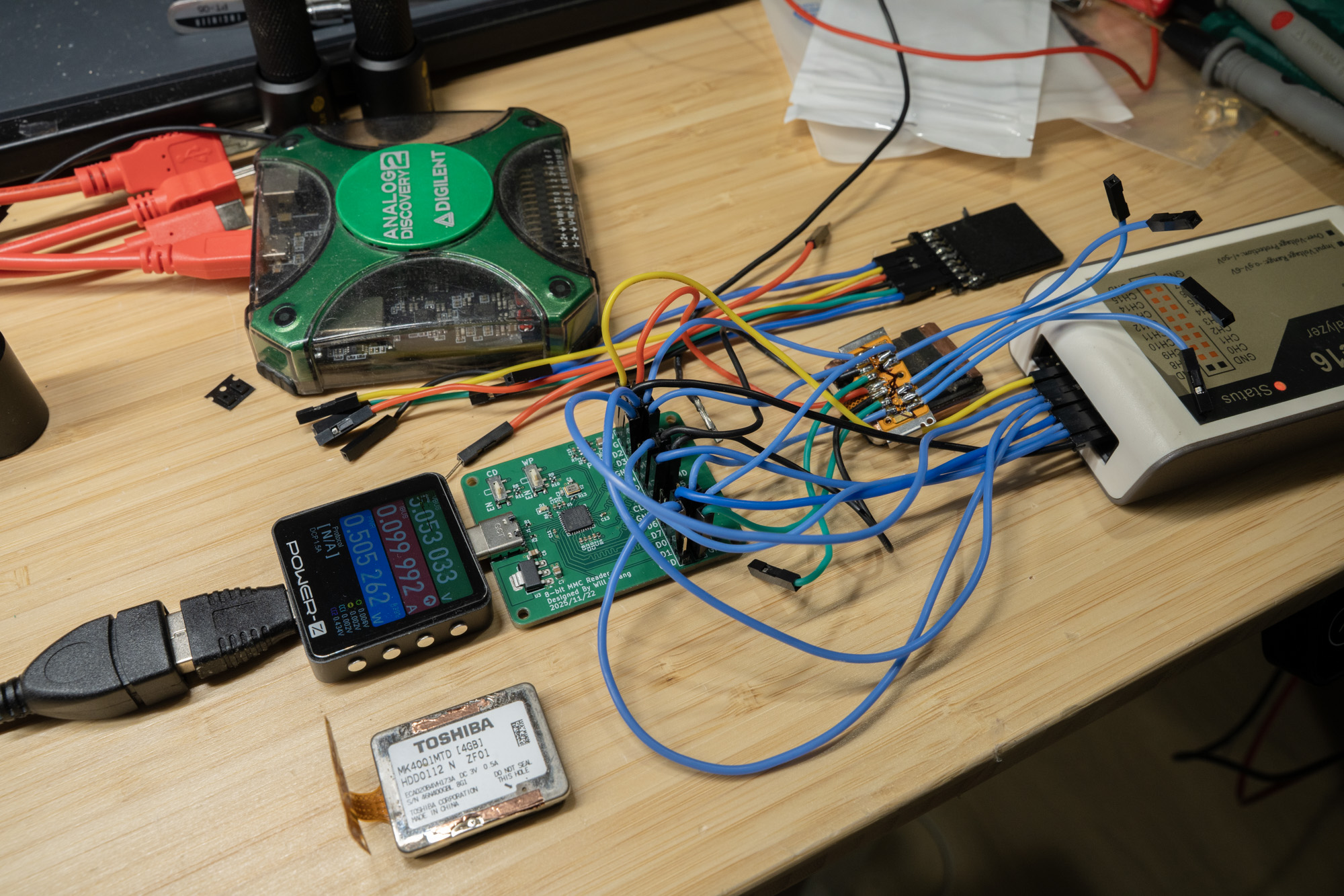
RP2040 Pico firmware that bridges a Toshiba MK4001MTD 0.85" SDIO microdrive as a USB Mass Storage device.
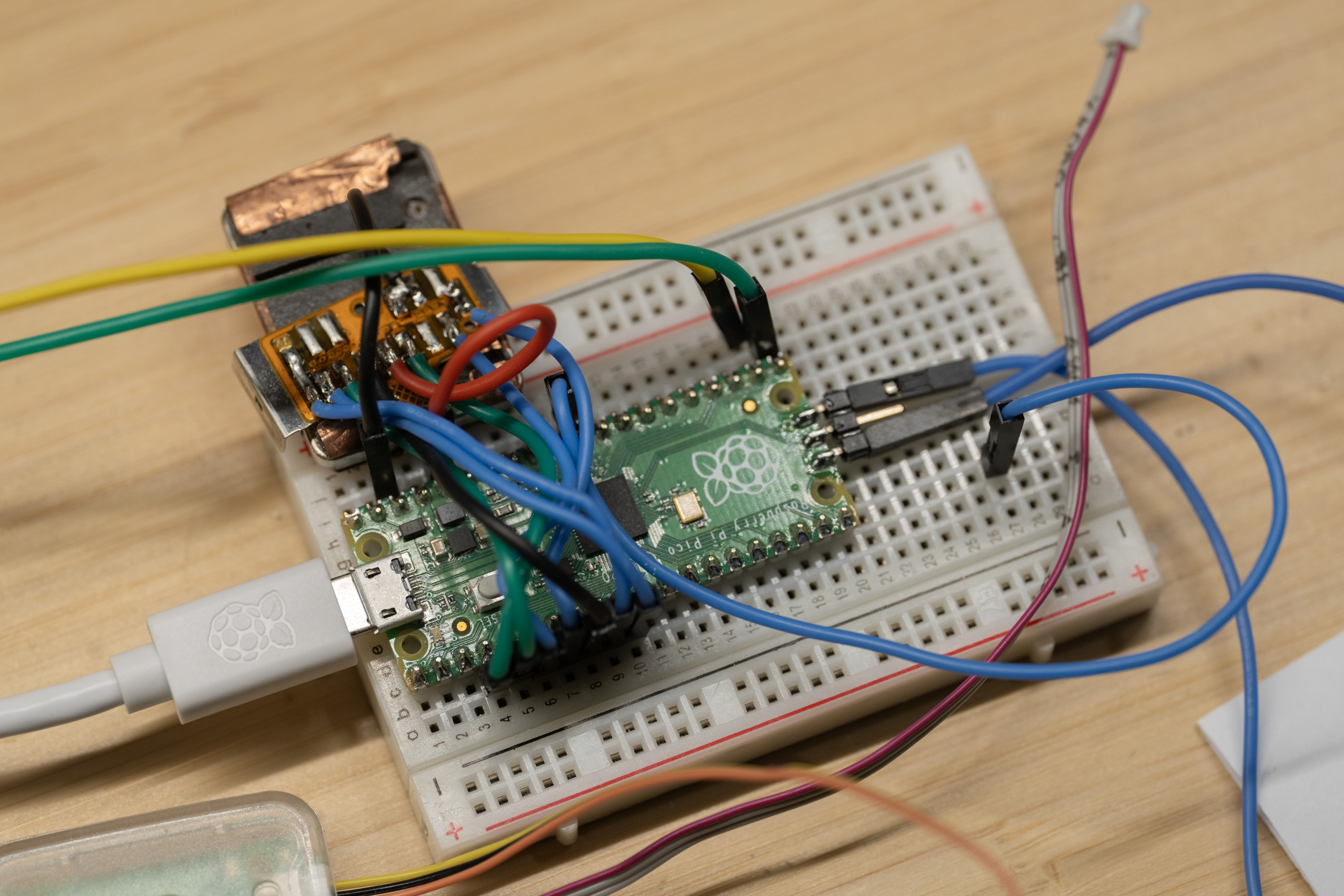
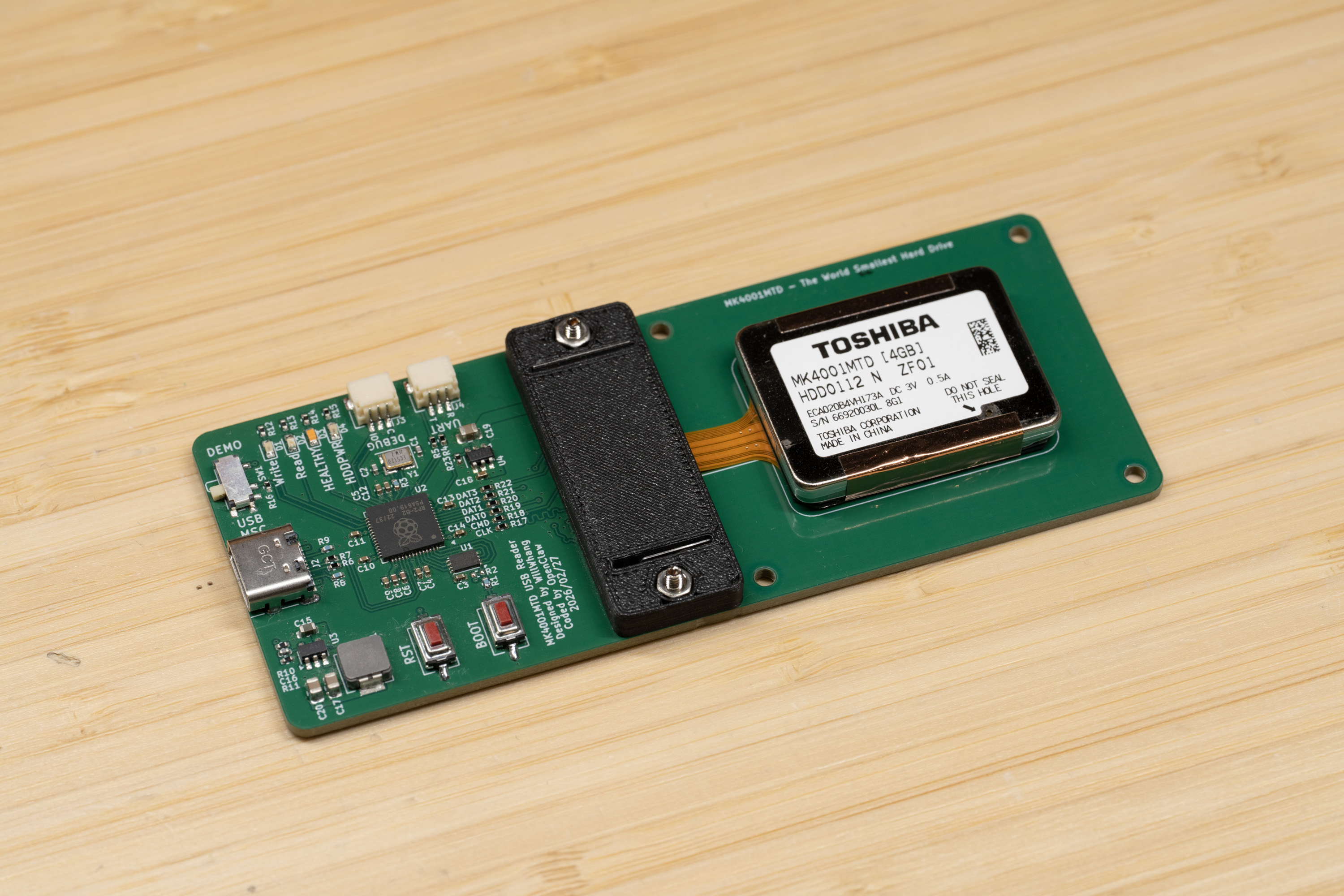
The MK4001MTD is a 4 GB Microdrive originally used in the Nokia N91 music phone and some other devices, like MP3 players or USB drives, back when flash storage was still quite expensive.
You might have seen introductions claiming this drive uses the MMC protocol, but that’s actually incorrect. I’ve been investigating this for a while: I tried building an 8-bit MMCplus card reader and tested different SD/MMC readers without success. As a last resort, I bought a Nokia N91 to capture logic traces and confirm what protocol it actually uses.
Here is the photo when I was trying to use it with my 8bit-MMCPlus reader board, and it turns out it is not MMC :(
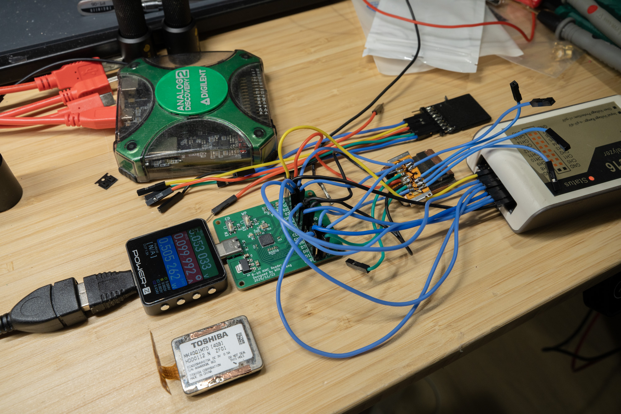
So I end up getting N91 to collect traces:
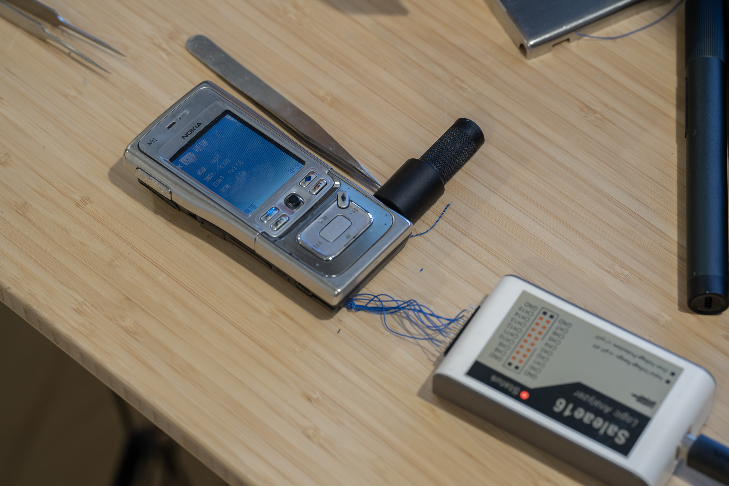
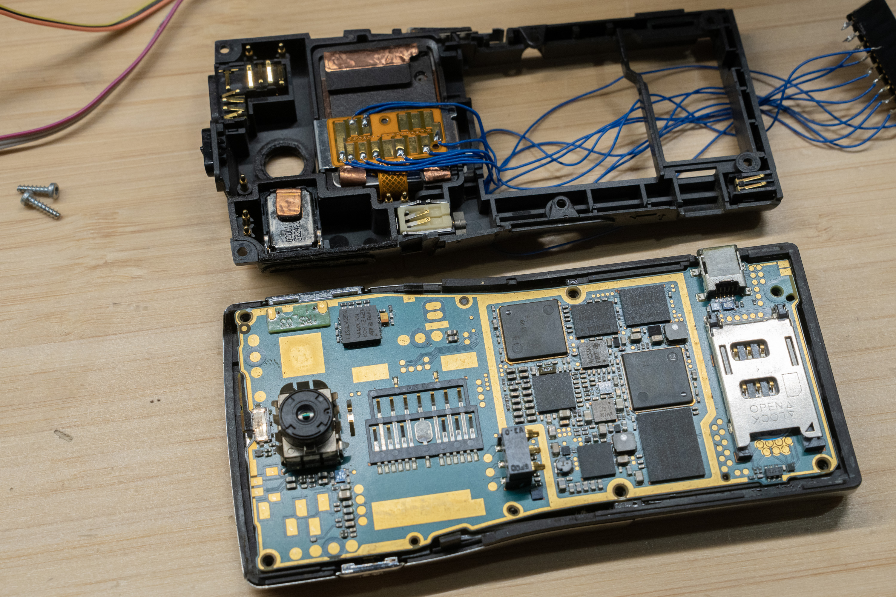
Unlike standard ATA/CF Microdrives, it uses an SDIO interface with ATA commands tunneled through CMD52/CMD53. No existing driver supports this protocol, so this firmware implements the full stack from scratch.
This surprised me, because there is an SDIO-to-ATA standard called CE-ATA. But if you look closely at the release timeline, CE-ATA came later than this drive. As a result, this drive relies entirely on SDIO commands, and CE-ATA is not available. CE-ATA has two new cmd CMD60/CMD61 and utilize CMD12/39, but you can see from the traces it is not using any of those.
The second hardware point to mention is that another piece of misinformation floating around—claiming it’s an 8-bit MMCPlus card—is not only untrue, but the pinout doesn’t follow the MMC standard either. You can find the Nokia N91 service manual with some documentation on the pinout: while the pin numbering follows the MMCPlus standard, the pin mapping does not. This is an important detail if you’re wiring it yourself: it uses the same MMC connector, but the pin mapping is different, more in the Hardware section.
Finally, note that this is co-developed with Claude/OpenClaw. I collected the logic traces manually and set up a closed-loop test station for OpenClaw to iterate on development—analyzing the traces and implementing features. The documentation will mostly be written by Claude; I’ll add my notes inline as well. I’ve also read and double-checked the documentation myself, and it should be reliable and easy to follow.
For insights into the analytics on N91 trace, it is under /docs/N91_TRACE_ANALYSIS.md, I've also put the N91 service manual there along with the raw logic traces.
See more in the blog post here: https://www.willwhang.dev/Reading-MK4001MTD/
See it in activity here: https://youtu.be/GC4xil3_Bbc
Fully functional USB mass storage with PIO-accelerated reads/writes and idle power management.
USB Host ←→ USB MSC (TinyUSB) ←→ ATA Layer ←→ SDIO Layer (PIO) ←→ MK4001MTD
The firmware has four layers:
USB MSC (msc_device.c) — TinyUSB Mass Storage Class. Translates SCSI READ(10)/WRITE(10) into ATA sector operations. 32 KB EP buffer, batching up to 64 sectors per USB transfer. Drive I/O is overlapped with USB in both directions, like a real ATA-USB bridge with a caching disk: a sequential-read prefetcher fetches the next chunk while the previous one streams to the host, and writes are staged and flushed while USB receives the next piece. The device advertises its write cache (Caching mode page, WCE=1 — hosts report "Write cache: enabled" and issue SYNCHRONIZE CACHE at fsync/unmount/suspend, which the firmware honors). A failed background flush surfaces as MEDIUM ERROR on the next WRITE or SYNCHRONIZE CACHE; writes to known-bad sectors take a strict synchronous path.
ATA-over-SDIO (ata_sdio.c) — Implements ATA commands (IDENTIFY, READ SECTORS, WRITE SECTORS) by writing to ATA registers mapped into SDIO function 1 address space via CMD52, and transferring sector data via CMD53. 3-tier retry logic at CMD, data, and ATA levels.
PIO SDIO (sdio_pio.c, sdio.pio) — Hardware-accelerated SDIO using RP2040's PIO peripheral (4-bit bus at 10 MHz, 4 PIO cycles per bit with input synchronizers bypassed). Three PIO programs share a single state machine via dynamic program swapping:
Pin/Power (sdio_hw.c) — GPIO initialization and HDD power control. All SDIO communication uses PIO.
Human notes: Interestingly, Claude was really reluctant to implement SDIO in PIO, and a lot of development cycles were wasted bouncing back and forth between PIO and bit-banging.
The MK4001MTD presents itself as an SDIO card with one I/O function. Standard SDIO card initialization (CMD5/CMD3/CMD7) sets up the bus, then ATA registers are accessed through SDIO commands:
Register access (CMD52): Each ATA register is mapped to a function 1 address:
Data transfer (CMD53): Sector data is transferred by issuing CMD53 in block mode targeting the DATA register (address 0x00). For multi-sector reads, a single CMD53 with block_count=N transfers N × 512 bytes in one SDIO multi-block transaction.
Interrupt signaling: The drive signals sector readiness by asserting an SDIO interrupt (INT_PENDING bit 1 in CCCR register 0x05). Reading the ATA STATUS register clears the interrupt.
For a 16-sector read:
1. Write ATA registers via PIO CMD52:
SECCOUNT=16, LBA_LO/MID/HI, DEV/HEAD=0xE0, CMD=0x20
2. Poll STATUS via CMD52 until DRQ (bit 3) is set
3. Swap PIO to DAT read program
4. Send CMD53: block_mode=1, fn=1, addr=0x0000, block_count=16
5. PIO DAT read: for each of the 16 blocks:
a. Wait for start bit (all DAT lines low)
b. DMA 1024 nibbles (512 bytes) from PIO RX FIFO to buffer
c. Wait for SM to finish clocking CRC+end nibbles (poll SM PC)
d. Repack nibbles → bytes in-place
6. Swap PIO back to CMD program
For a 16-sector write:
1. Write ATA registers via PIO CMD52:
SECCOUNT=16, LBA, DEV/HEAD=0xE0, CMD=0x30
2. Poll STATUS via CMD52 until DRQ (bit 3) is set
(STATUS 0xD8 = BSY+DRQ treated as DRQ-ready, per N91 trace)
3. Swap PIO to DAT write program
4. Send CMD53: block_mode=1, fn=1, addr=0x0000, block_count=16
5. PIO DAT write: for each of the 16 blocks:
a. Precompute CRC16-CCITT per DAT line (4 independent CRCs)
b. Build nibble stream: start(0x0) + data(1024 nibbles) + CRC(16) + end(0xF)
c. DMA nibble stream to PIO TX FIFO
d. PIO clocks out all nibbles, then:
- Switches DAT to input
- Clocks 16 cycles for CRC status from card
- Polls DAT0 until card releases busy
- Fires IRQ 0 to signal block completion
6. Swap PIO back to CMD program
The RP2040 PIO has 32 instruction slots per block. Our three programs total 55 instructions, so they can't coexist. Instead, a single SM0 on PIO0 is used, and programs are swapped by writing directly to PIO instruction memory:
static void load_program_raw(const pio_program_t *program) {
for (uint i = 0; i < program->length; i++)
pio->instr_mem[FIXED_OFFSET + i] = program->instructions[i];
}
This bypasses the SDK's pio_add_program/pio_remove_program allocator. Program swap takes ~1 µs. Each swap is followed by a program-specific reinit that sets pin mappings, shift direction, and clock divider.
Analysis of Nokia N91 logic traces reveals aggressive power management:
The firmware replicates this behavior with a configurable idle timeout:
#define IDLE_STANDBY_MS 5000 // in main.c
Two paths trigger HDD power gating:
Both paths send ATA STANDBY IMMEDIATE (0xE0) to flush the write cache and park heads, then cut power via GP9.
Wake sequence (triggered by first READ/WRITE after gate):
When a multi-sector transfer hits a bad sector:
STATUS/ERROR bits instead of collapsing the failure into a generic DRQ timeoutMEDIUM ERROR (read: 03/11/00, write: 03/0C/00)Point 6 is not academic: this drive had a long-standing unreadable sector at LBA 1952 (READ: ST=0x51 ERR ERR=0x40 UNC). Once the bridge allowed a write to actually reach it, the drive rewrote the sector and it has read back cleanly since:
[ATA] FAST-RD: ST=0x51 ERR ERR=0x40 UNC LBA=1952
[MSC] BAD SECTOR read LBA=1952
[MSC] Bad sector LBA=1952 repaired by write
arm-none-eabi-gcc)The SDK version is locked: if PICO_SDK_PATH is set (environment or
CMake variable) it is used and its version is checked against the pin —
a mismatch fails the configure with instructions (override with
-DMK4001_ALLOW_SDK_MISMATCH=ON). With no PICO_SDK_PATH at all, the
pinned SDK release is fetched from GitHub automatically at configure
time, so a bare git clone && cmake && make is fully reproducible.
The firmware needs a patched TinyUSB MSC class driver (app sense data
preserved on read/write errors + a Caching mode page with WCE=1). That
file is vendored in this repo at lib/tinyusb_patched/msc_device.c —
the build automatically compiles it instead of the SDK's copy, so no SDK
surgery is ever needed. The diff against upstream TinyUSB (0.18.0, as
bundled with pico-sdk 2.2.0) is in lib/tinyusb_patched/; the SDK pin
exists precisely because this vendored file must track the SDK's TinyUSB.
cd /home/pi/mk4001_bridge/build
cmake ..
make -j4
sudo openocd -f interface/cmsis-dap.cfg -f target/rp2040.cfg \
-c "adapter speed 1000" -c "init" -c "reset halt" -c "sleep 200" \
-c "program /home/pi/mk4001_bridge/build/mk4001_bridge.elf verify" \
-c "reset run" -c "exit"
Note: GP0 and GP1 are dead on this specific Pico unit. All SDIO pin assignments are shifted +2.
Human notes: Claude was wrong here because it didn’t realize that GP0 and GP1 were being used for the UART terminal in its build configuration. It kept forgetting this, to the point where I just moved the SDIO GPIOs off that UART.
HDD_PWR isn’t necessary. You don’t have to power-cycle the drive to use it; it’s more of a development convenience for resetting the HDD when a lot of things are hard-coded. That said, if you want power savings, you can use that signal, but it can handle warm reset without any issue.
You’ll see debug messages over UART. They’re not going through USB-CDC because it was easier for Claude to set up a separate UART-to-USB logging link that doesn’t disconnect or become unstable during early development.
The UART log also reports the drive temperature every 30 seconds while the drive is active ([TEMP] drive temperature: 29 C). The sensor was discovered by reverse-engineering the Toshiba vendor command 0xC2 — the N91 reads it at the start of every drive session to enforce its HDD operating-temperature limits. Details in docs/N91_TRACE_ANALYSIS.md §4.
Here is a example of the log:
========================================
MK4001MTD USB Bridge v0.11
SDIO-ATA → USB Mass Storage (PIO)
========================================
[MAIN] Pre-delay 5000ms...
[PIO] Init OK: clkdiv=3.12 (~10.0 MHz), CMD@0
[MAIN] Power cycling HDD...
[SDIO] HDD power OFF
[SDIO] HDD power ON
[MAIN] SDIO init (PIO)...
[SDIO] CMD5 ready (OCR=0x901F8000)
[SDIO] RCA=0x0001
[SDIO] fn1 ready (attempt 0)
[MAIN] ATA IDENTIFY...
[ATA] IDENTIFY complete
Model: [TOSHIBA MK4001MTD]
Serial: [ 763B004HA]
Firmware: [VH173A]
Sectors: 7862400 (3839 MB)
SMART: not supported (supported=0, enabled=0)
IDENTIFY: W0=0040 W47=0000 W49=0000 W59=0000
ATA W80=0000 Cmd W82=0000 W83=0000 W84=0000
En W85=0000 W86=0000 W87=0000 W89=0008 W128=0001
[DIAG] === Drive Diagnostics ===
[DIAG] Standard SMART: not supported (IDENTIFY W82 bit0 = 0)
[DIAG] Toshiba vendor CMD 0xC2:
FEAT=0x01 unknown_01 → SC=00 LBA=02/00/00 ST=50
FEAT=0x02 unknown_02 â SC=00 LBA=02/00/00 ST=50
FEAT=0x03 unknown_03 → SC=00 LBA=02/00/00 ST=50
FEAT=0x04 unknown_04 → SC=00 LBA=02/00/00 ST=50
FEAT=0x10 diag_10 (LBA_LO varies) → SC=00 LBA=00/00/00 ST=50
FEAT=0x11 diag_11 → SC=00 LBA=00/00/00 ST=50
FEAT=0x12 diag_12 (LBA_LO varies) → SC=00 LBA=01/00/00 ST=50
FEAT=0x20 query_20 (N91: SC=0xFF always) → SC=FE LBA=00/FF/00 ST=50
FEAT=0x21 query_21 (N91: SC varies per boot) → SC=1B LBA=00/FF/00 ST=50
[MAIN] MBR: valid 0x55AA
[MAIN] Warming up...
[MAIN] PIO OK, STATUS=0x50
[MAIN] Drive: 7862400 sectors (3839 MB)
[MAIN] Ready.
[PWR] Idle 5000ms → STANDBY + power gate
[PWR] STANDBY IMMEDIATE → power gate
[SDIO] HDD power OFF
Finally, here’s the wiring to the actual drive.
Here is a crop from the N91 schematic, you can map the pin number also.

Side note that this is a 3V drive but I think 3.3V is fine, mostly it is to save some level shifting work.
HW specifically designed for this drive is under /hardware!

# Check device appeared
lsblk -dno NAME,MODEL | grep MK4001
# Filesystem test — mount, copy files, verify
sudo mount /dev/sdX1 /mnt/mk4001
cp /tmp/testfile /mnt/mk4001/
sync
md5sum /tmp/testfile /mnt/mk4001/testfile # should match
sudo umount /mnt/mk4001
# Speed benchmarks (raw device, do NOT mount first — will corrupt filesystem)
# Use a safe offset past the filesystem or an unpartitioned drive
sudo dd if=/dev/sdX of=/dev/null bs=64k count=128 iflag=direct # read
sudo dd if=/dev/zero of=/dev/sdX bs=64k count=64 oflag=direct seek=1024 # write (offset past FS)
Human notes here, fun fact: When it first starts to do speed testing, it actually dd directly to the drive and damage the filesystems..... Thankfully it doesn't matter that much here during the developments but always keep in mind when you handle OpenClaw your setup.
I don't care.
| Metric | Value |
|---|
| Read speed | ~985 kB/s (USB full-speed limited) |
| Write speed | ~920 kB/s (USB full-speed limited, advertised write cache) |
| Raw SDIO-side speed | ~2.35 MB/s read / ~2.15 MB/s write (drive-limited) |
| Capacity | 3.75 GB (7,862,400 sectors) |
| Filesystem | FAT32 verified (mount/unmount/fsck clean) |
| Data integrity | Write+readback verified; per-block CRC16 on all 4 DAT lines |
| Idle standby | 5 s idle or USB suspend → STANDBY IMMEDIATE + power gate |
| Address | Register | Usage |
|---|
| 0x00 | DATA | CMD53 target for sector data |
| 0x01 | ERR/FEAT | Error (read) / Feature (write) |
| 0x02 | SECCOUNT | Sector count |
| 0x03 | LBA_LO | LBA bits 0-7 |
| 0x04 | LBA_MID | LBA bits 8-15 |
| 0x05 | LBA_HI | LBA bits 16-23 |
| 0x06 | DEV/HEAD | Device/Head + LBA bits 24-27 |
| 0x07 | CMD/STATUS | Command (write) / Status (read) |
| Pico GPIO | Function | Notes |
|---|
| GP2 | SDIO_CLK | Host clock output |
| GP3 | SDIO_CMD | Bidirectional command line |
| GP4 | SDIO_DAT0 | Data bit 0 |
| GP5 | SDIO_DAT1 | Data bit 1 |
| GP6 | SDIO_DAT2 | Data bit 2 |
| GP7 | SDIO_DAT3 | Data bit 3 |
| GP9 | HDD_EN | Drive power enable (HIGH=on) |
| GP12 | UART TX | Debug output @ 115200 |
| GP13 | UART RX | Debug input |
| GP16 | LED: HDD Power | Active low |
| GP17 | LED: HDD Healthy | Active low |
| GP18 | LED: Read | Active low |
| GP19 | LED: Write | Active low |
| File | Lines | Purpose |
|---|
main.c | 210 | Init, idle standby, USB suspend/resume |
msc_device.c | 400 | USB MSC callbacks, power gate wake, bad sector cache |
ata_sdio.c | 390 | ATA commands, error recovery, vendor diagnostics |
sdio_pio.c | 635 | PIO SDIO: CMD52, CMD53 read/write, program swap, CRC16 |
sdio_hw.c | 45 | Pin init + HDD power control |
sdio.pio | 200 | PIO assembly + C SDK init helpers |
led.h | 37 | LED helpers (GP16–GP19, active low) |
usb_descriptors.c | 77 | USB device/config/string descriptors |
tusb_config.h | 20 | TinyUSB config (MSC, 32KB EP buffer) |
| Version | Read | Write | Key Change |
|---|
| v0.1–v0.3 | 105 kB/s | 93 kB/s | Bit-bang SDIO, CRC16, retry logic |
| v0.5 | 374 kB/s | — | Single-SM PIO, direct instruction memory swap |
| v0.6 | 583 kB/s | 93 kB/s | Multi-block CMD53 reads, CRC clock drain fix |
| v0.8 | 588 kB/s | 274 kB/s | PIO writes, OSR flush fix |
| v0.9 | 475 kB/s | 371 kB/s | 64-sector chunks, CRC16 read verification |
| v0.10 | 453 kB/s | 329 kB/s | LED remap, HDD EN pin, UART on GP12/GP13 |
| v0.11 | ~450 kB/s | ~340 kB/s | HDD power gate, PIO wake, bad sector sense, USB suspend |
| v0.12 | ~985 kB/s | ~920 kB/s | Drive/USB overlap (read prefetch + advertised write cache with write-behind), pipelined PIO blocks, bswap DMA, 4-cycle PIO loops, SBC-style bad-sector semantics (write-repair), vendored TinyUSB MSC driver |