 sjgallagher2/am335xbootrom
Reverse engineering the TI AM3358 boot ROM

It's probably been eighteen months since I first got my hands a few Beaglebone Black boards, saved from the dumpster. Unfortunately, the boards didn't work right away. Now, this was my first time working with one of these boards, or any single board computer for that matter, so I wasn't sure if the problem was something I was doing, or something wrong with the boards themselves (perhaps why they were headed for the dumpster in the first place). It has taken me quite a long time, and a large amount of effort, to get these boards to actually start booting, but damn it, I did it. And here's what I learned along the way.
I've included some utilities in this repo, along with an xml file exported from Ghidra which has all the symbols I've obtained so far from reversing. I used this post to export without the actual firmware, to avoid any copyright issues, just in case. If you want to debug the boot ROM yourself, you'll already have the JTAG hooked up, so you can dump the boot ROM (from 0x20000 to 0x2BFFF) yourself.
To load the symbols:
0x20000 and you can set the block name to bootrom.main(), or the MMC/SD card boot handler.To begin with, I knew these were custom versions of the standard beaglebone black, so early on I determined that it could be something missing on the board itself, like a board identifier. What I saw when booting a standard SD card formatted with balenaEtcher, was just nothing. I expected the LEDs on the board to start blinking, and I expected that connecting up a UART to USB cable would allow me to see the U-Boot process. However, the UART was quiet. If I removed the SD card, it would output the letter C over and over, which is expected behavior for a UART/serial boot. It was definitely trying to boot, and the SD card was altering this behavior, but I didn't have any more visibility. Most troubleshooting on the web took the U-Boot output as a starting point to diagnose problems. I guess I wasn't going to have that luxury.
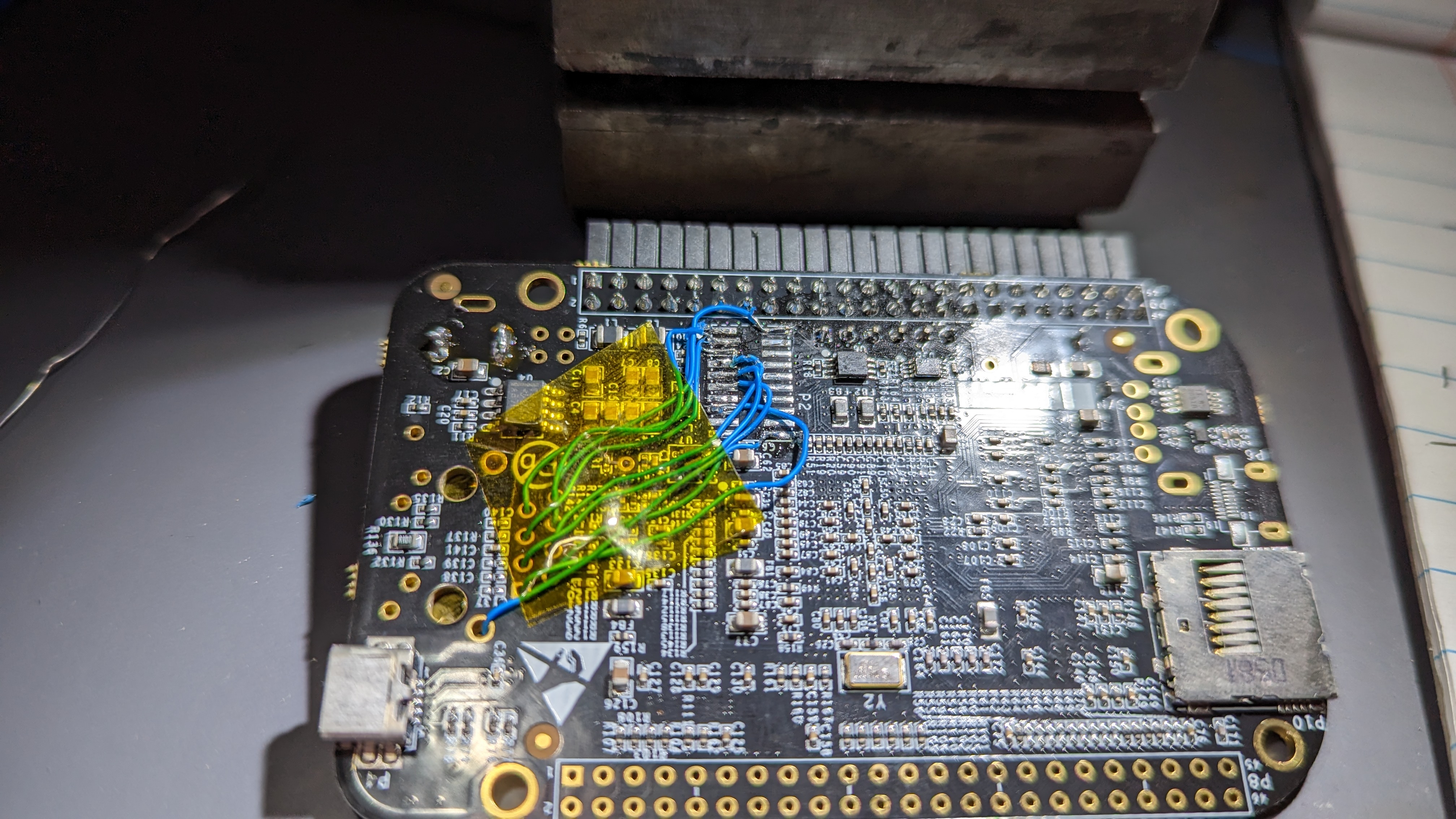
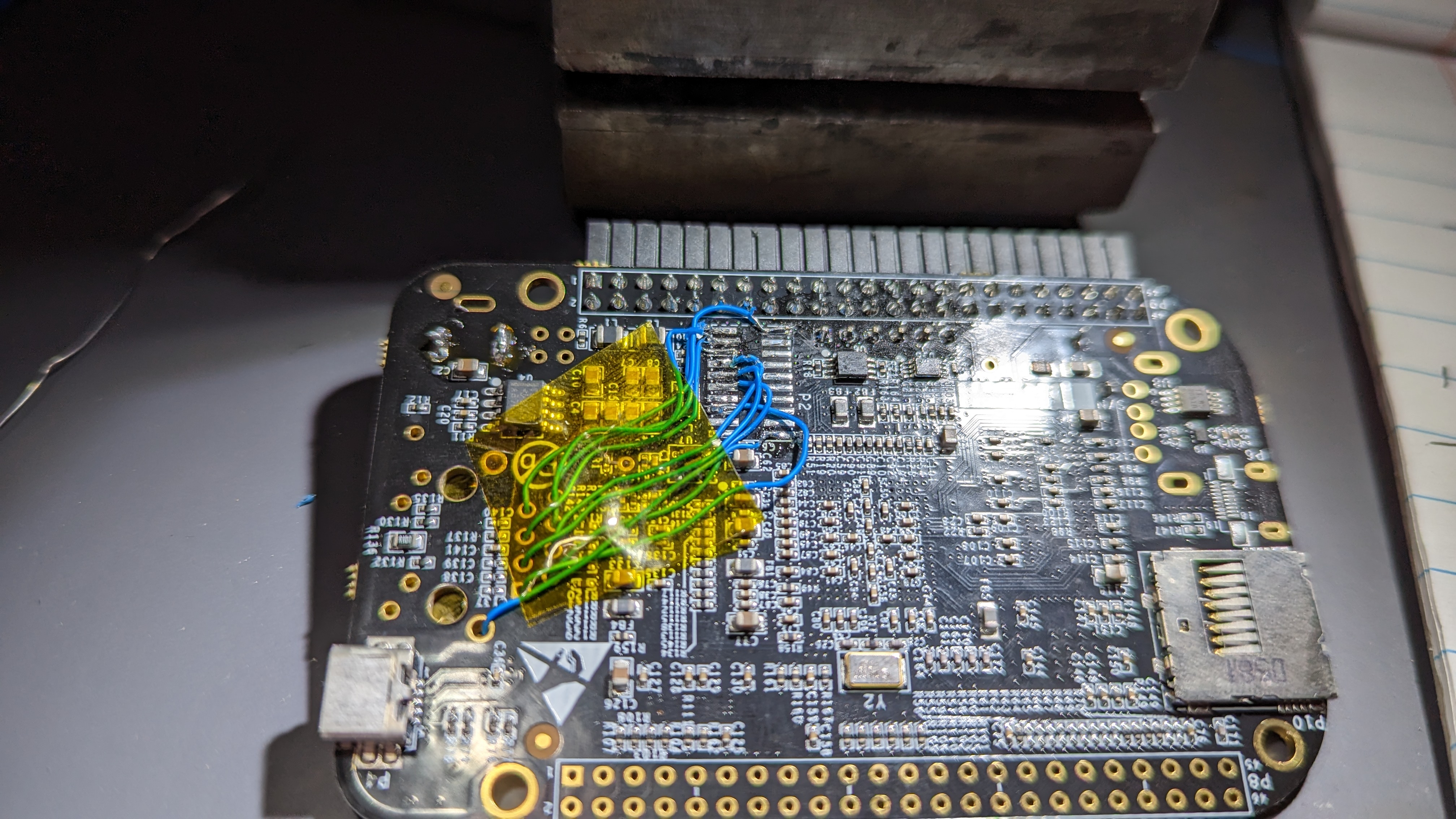
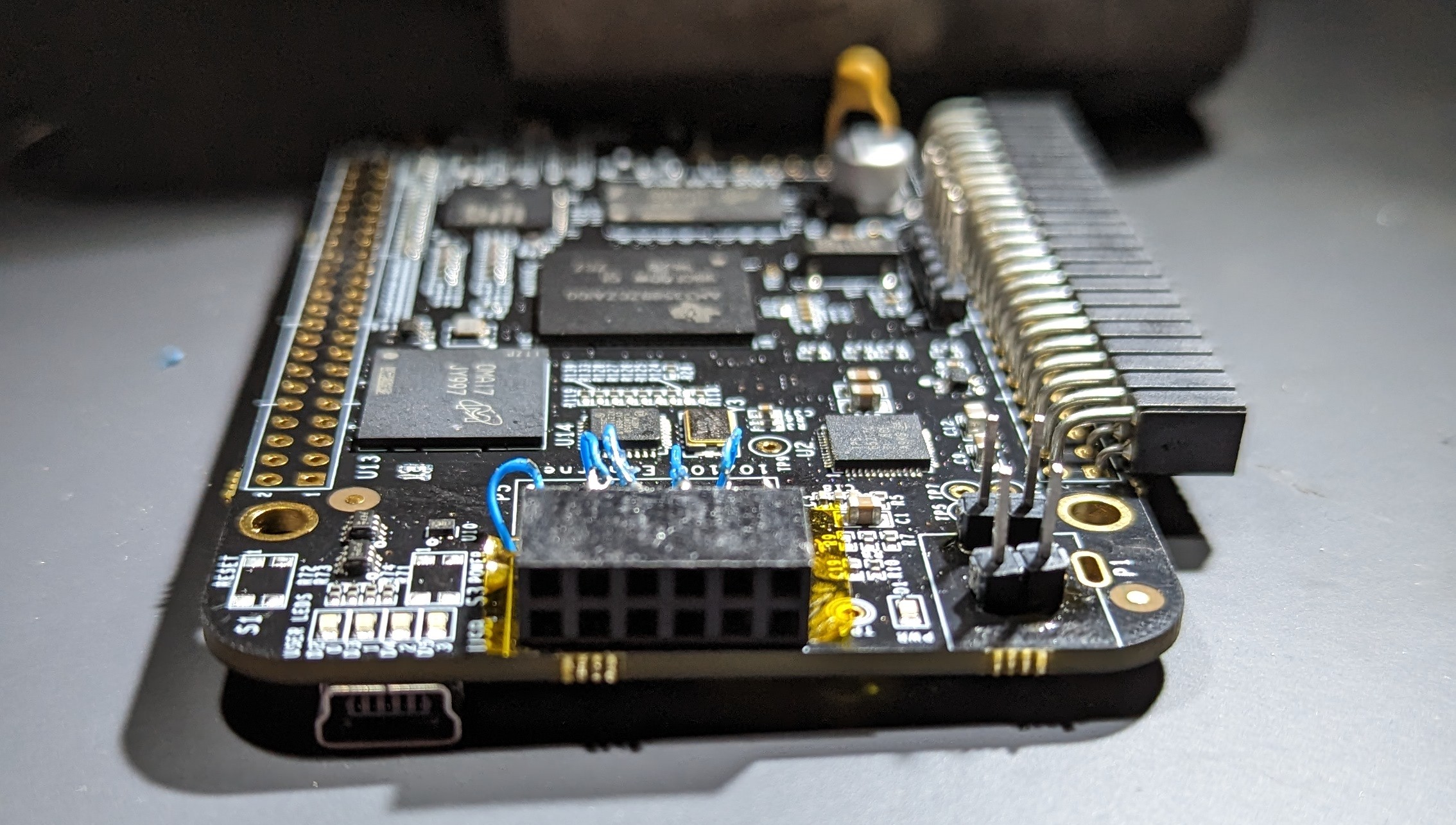
I figured at this point that it would be worthwhile to connect up a debug probe. Unfortunately, I didn't have a matching header for the existing footprint come so I made my own.
The beaglebone board has a header with designator P2 which breaks out the JTAG connections. I connected some wires to this up to a female header so that I can talk to it through my J-Link.
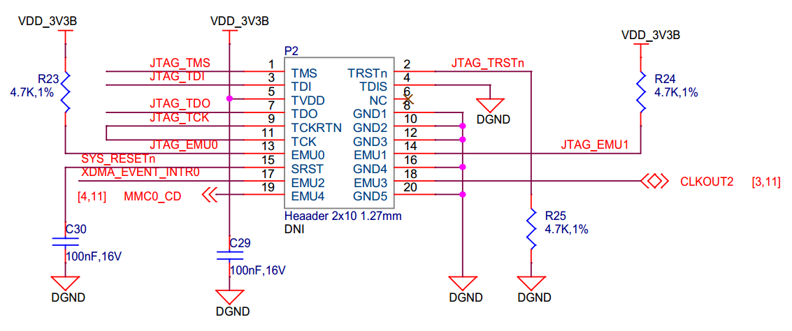
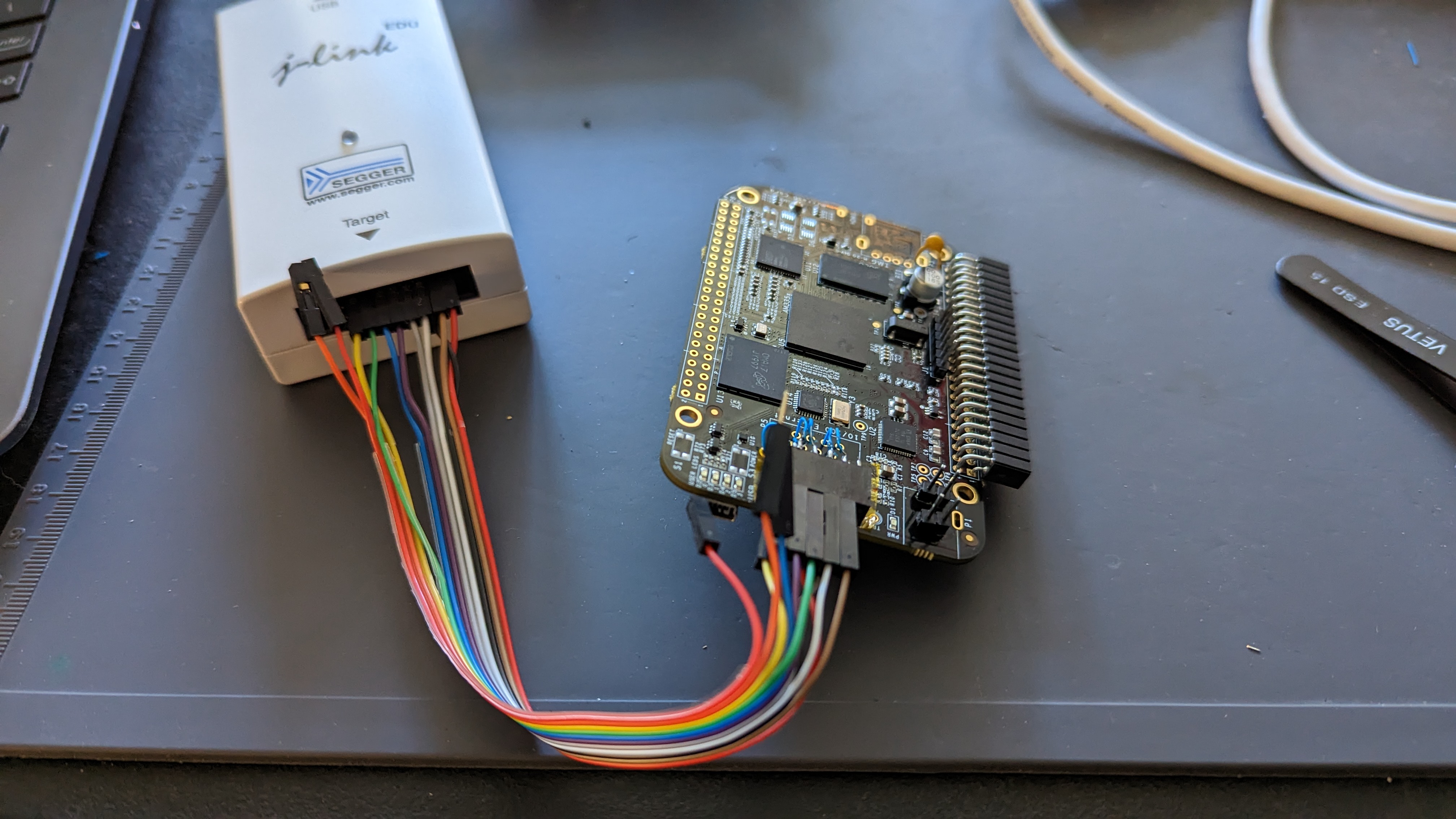
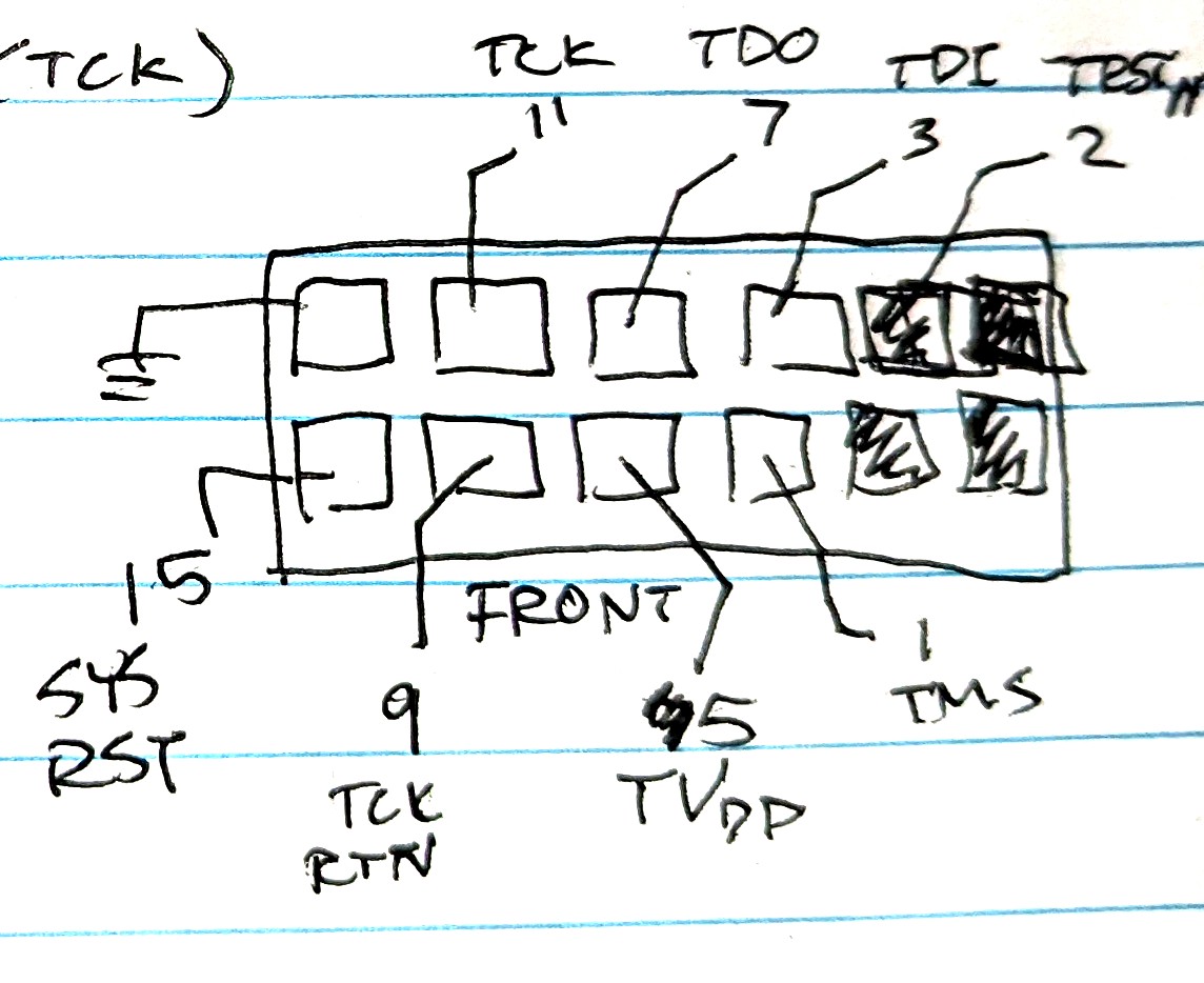
Launching into Ozone (the Segger debugger) I configured the J-Link and started by just trying to find the entry point. I had thought that a reset-halt would put me where I needed to be, which was how I came to the (incorrect) assumption that the entry point was 0x2148a, although I certainly noticed that this wasn't consistent. Later, I realized that the AM335x boards don't really play well with the J-Link's reset-halt, so there was actually a delay of maybe a few hundred clock cycles, landing me somewhere inside a boot handler, indeterministically. (I eventually got around this by writing a GEL file for TI's Code Composer Studio which supports J-Link debugging - on reset, the PC register is set to the reset handler, the registers are cleared, and the instruction mode is forced to ARM.)
From a thread on the TI forums (AM335x: TI employees, where can I get the ROM Bootloader source code/symbols?) I picked up a couple debugging symbols: SPI Initialize at 0x231e0, SPI ReadSectors at 0x23230, and 0x24bfa is a routine performing a UART read. That's a nice bit of help I guess. I noticed that the boot failed by ending up in an infinite loop at 0x402f0440, a dead loop. Hmm, quite far off from the rest of the boot ROM, must be in RAM or something. It's probably time to go over to the technical reference manual (TRM)!
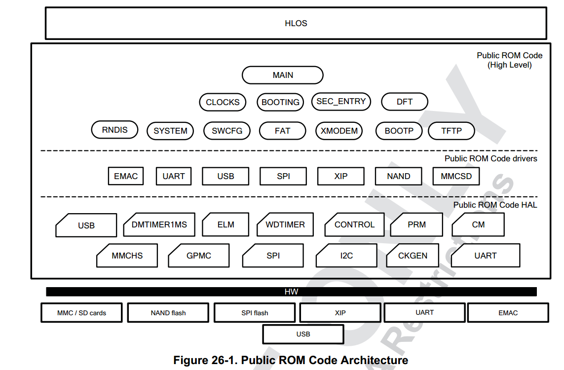
Chapter 26 of the TRM contains a ton of information on booting. We get the following view of the boot ROM:
Description:
The architecture of the Public ROM Code is shown in Figure 26-1. It is split into three main layers with a top-down approach: high-level, drivers, and hardware abstraction layer (HAL). One layer communicates with a lower level layer through a unified interface. The high level layer is in charge of the main tasks of the Public ROM Code: watchdog and clocks configuration and main booting routine. The drivers layer implements the logical and communication protocols for any booting device in accordance with the interface specification. Finally the HAL implements the lowest level code for interacting with the hardware infrastructure IPs. End booting devices are attached to device IO pads.
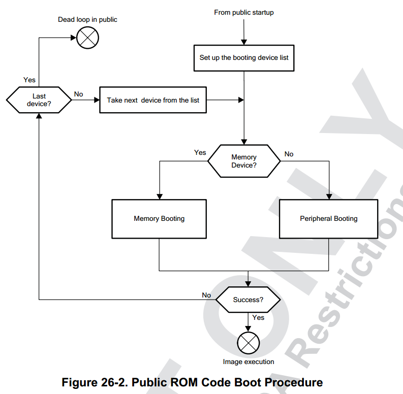
Figure 26-2 illustrates the high level flow for the Public ROM Code booting procedure. On this device the Public ROM Code starts upon completion of the secure startup (performed by the Secure ROM Code). The ROM Code then performs platform configuration and initialization as part of the public start-up procedure. The booting device list is created based on the SYSBOOT pins. A booting device can be a memory booting device (soldered flash memory or temporarily booting device like memory card) or a peripheral interface connected to a host. The main loop of the booting procedure goes through the booting device list and tries to search for an image from the currently selected booting device. This loop is exited if a valid booting image is found and successfully executed or upon watchdog expiration. The image authentication procedure is performed prior to image execution on an HS Device. Failure in authentication procedure leads to branching to a “dead loop” in Secure ROM (waiting for a watchdog reset).
Memory map! Exception vectors! Flow-charts! Lots of information in this section. My job just got a lot easier.
At this point I used the JTAG probe to download the firmware into a couple different files, and started loading things into Ghidra. There didn't seem to be any SVD files or other register mappings available in a convenient format, which is really unfortunate, because that means I need to define the memory regions and registers and everything manually. This was a tedious process, but after a while I had a python script I could use to load symbols into Ghidra for the the AM3358. One less thing to worry about!
It seems like the files I have can be mapped as:
