
Skip to content
KitploitKITPLOIT
ToolsBlog
Submit
ToolsBlog
Submit

Hacking, PenTest, and Cybersecurity Tools for Your Security Arsenal!

Kitploit is a directory of hacking, cybersecurity, and pentesting tools. Discover the latest project updates to find vulnerabilities, analyze systems, automate testing, and strengthen your security.

··Feeds·Contact·Privacy·© 2026 Kitploit

Tool Directory

Categories

View all categories
Loading categories
amradio | Kitploit
Tools/GitHubGitHub/park07/amradio
Embedded Systems SecurityHardware HackingHardware SecurityHardware & IoT SecurityPapers & ResearchLearning & EducationFirmware Analysis
GitHubpark07/amradio

amradio

View Repository
3315 months agoReviewed by Kitploit

Most Popular

View all →

Discover the most used tools by our community.

Explore all tools

Browse our collection of tools

View all tools →
Share

AM Radio Break-in System

A 12-channel AM radio broadcast system using Red Pitaya FPGA for emergency alert transmission in unmanned tunnels.

Why AM radio in a tunnel? During construction and maintenance, vehicles with standard AM radios transit through tunnels that have no mobile coverage. AM signals propagate along tunnel structures via leaky feeder cables, and receivers are cheap, robust, and already present in every vehicle. The system broadcasts pre-recorded emergency alerts across multiple frequencies so that any AM radio tuned to any station in the band will receive the message. A hardware watchdog ensures RF output is killed if the control system fails — because automatically restarting a transmitter in an unmanned tunnel is not an acceptable failure mode.


Channels: 12 Platform: Red Pitaya Backend: Rust Frontend: JavaScript Formal Verification: 14/14 PASS


Features

FeatureStatus
12 simultaneous carrier frequencies✅
Runtime frequency configuration (no hardware changes)✅
AM modulation with pre-recorded audio✅
Dynamic power scaling✅
MVC architecture (Rust + JavaScript)✅
Event-driven pub/sub via event bus✅
Stateless UI — device is source of truth✅
Network polling & auto-reconnect✅
Fail-safe hardware watchdog (5s timeout)✅
Formal verification (14 properties, 6 covers, all proven)✅

Architecture

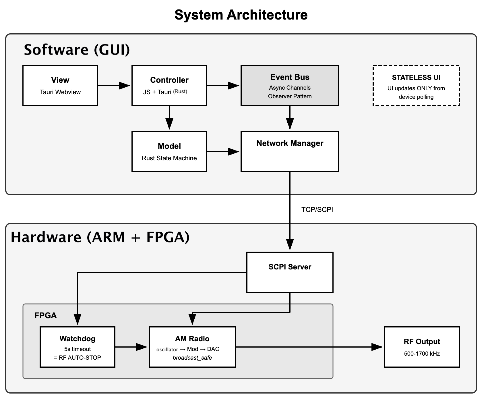
System Architecture

Software Layer

  • Framework: Rust (Tauri) backend + JavaScript frontend
  • Architecture: MVC with event-driven pub/sub
  • Model (model.rs): NetworkManager handles TCP/SCPI, device state, 500ms polling, auto-reconnect with exponential backoff
  • View (view.js, index.html): Stateless — only renders confirmed device state. Never assumes hardware state.
  • Controller (controller.js): Handles user input, publishes events to bus
  • Event Bus (event_bus.rs, event_bus.js): Components communicate through a central bus instead of calling each other directly. Rust emits events to JS frontend via Tauri bridge.
  • State Machine (state_machine.rs): IDLE → ARMING → ARMED → STARTING → BROADCASTING → STOPPING. Intermediate states prevent invalid transitions.
  • Source of Truth: The device, not the software. UI only updates after hardware confirms.

Hardware Layer

  • NCO: 12 Numerically Controlled Oscillators generate carrier frequencies (505–1605 kHz)
  • AM Modulator: Combines audio source with each carrier
  • Dynamic Scaling: Output power adjusts based on enabled channel count
  • Audio Buffer: BRAM stores pre-recorded emergency messages (16,384 sample buffer at ~5 kHz playback rate). AXI audio loader available for runtime loading.
  • Watchdog Timer (wd.v): Hardware fail-safe — if GUI heartbeat stops for 5 seconds, RF output is killed and latched. Only manual operator reset restores output.
  • SCPI Server (am_scpi_server.py): Runs on Red Pitaya, parses text commands, converts frequencies to phase increments, writes to FPGA registers via /dev/mem.

Signal Generation Flow

root@kitploit:~
GUI click → invoke("set_frequency") → model.rs sends "FREQ:CH1 700000" over TCP
→ am_scpi_server.py converts to phase_inc = (700000 × 2³²) / 125MHz
→ writes to FPGA register via /dev/mem → NCO generates carrier → AM modulates → RF output

Formal Verification

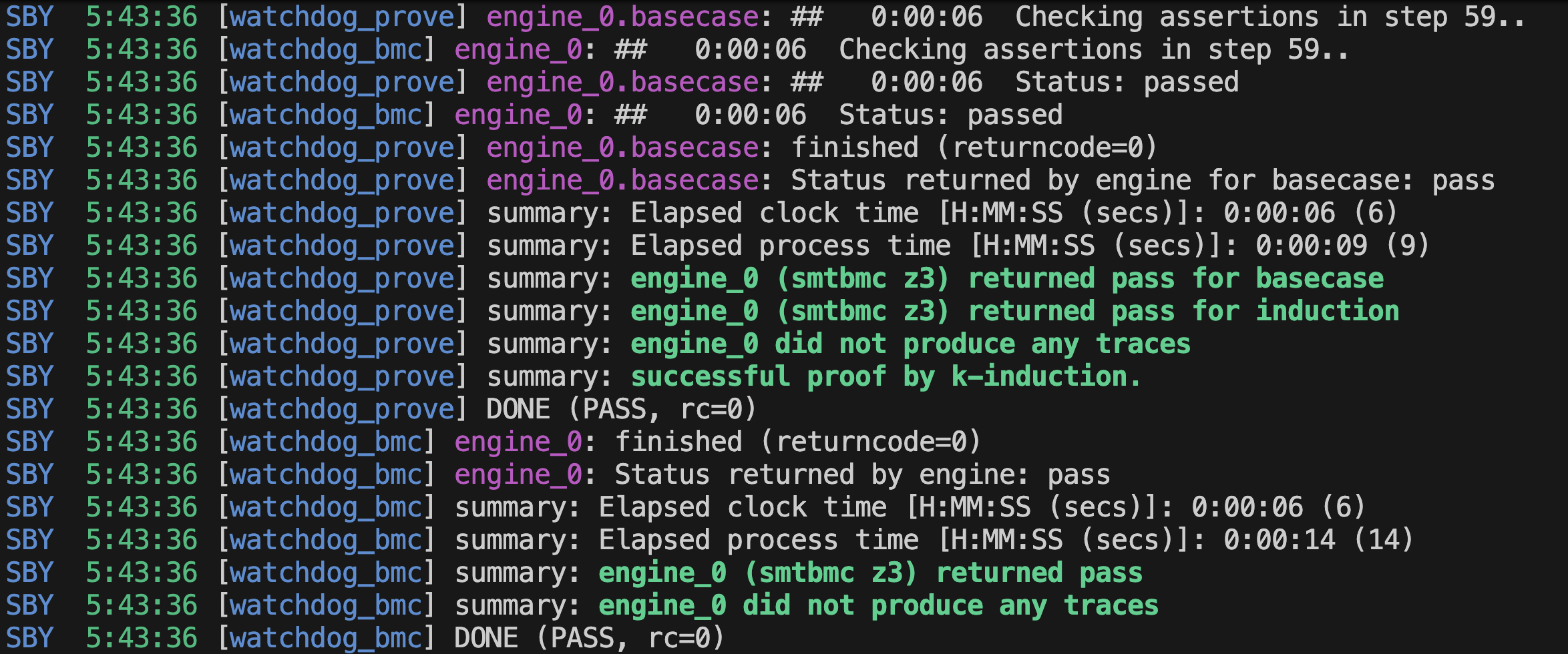
The watchdog timer is mathematically proven correct using bounded model checking and k-induction (SymbiYosys + Z3 SMT solver). Unlike simulation-based testing which checks individual scenarios, formal verification proves correctness across every possible input, in every possible state, for all time.

14 Safety Properties (All PASS)

6 Cover Scenarios (All Reached)

Running Verification

root@kitploit:~
cd fpga/formal/
sby -f wd.sby

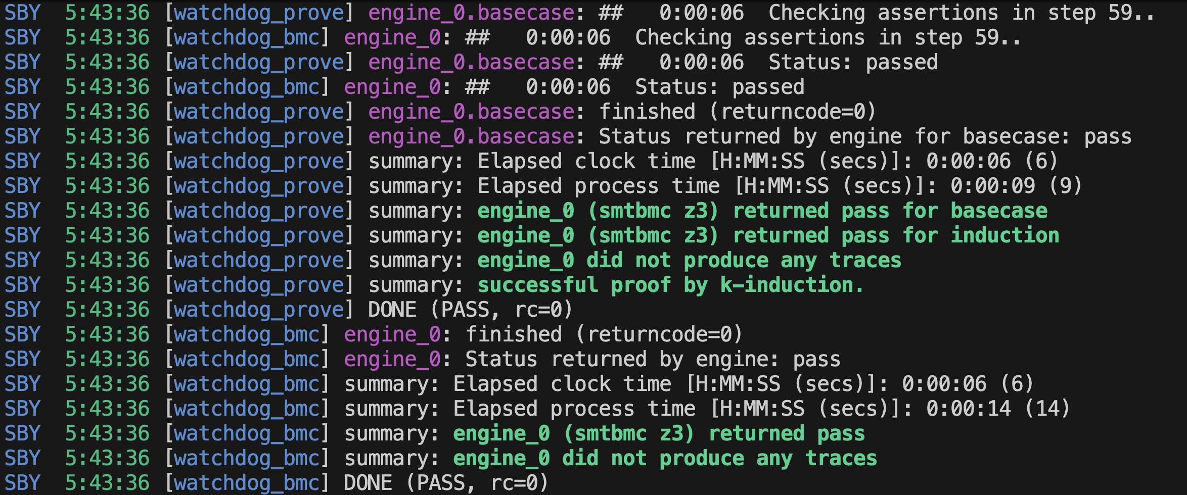
Expected output: SymbiYosys Verification Output
root@kitploit:~
SBY [wd_prove] DONE (PASS, rc=0)
    summary: successful proof by k-induction.
SBY [wd_cover] DONE (PASS, rc=0)
    summary: 6/6 cover statements reached.

Scalability

Verification uses CLK_FREQ=1, TIMEOUT_SEC=5 to keep state space tractable. Production uses CLK_FREQ=125000000. The RTL is parameterised — same if/else logic, same state transitions. Proof at reduced scale implies correctness at production scale.

See fpga/formal/README.md

Requirements

Hardware

  • Red Pitaya STEMlab 125-10
  • AM Radio receiver(s) for testing
  • Ethernet cable (for Red Pitaya connection)

Software

Formal Verification (optional)

  • SymbiYosys
  • Yosys
  • Z3 SMT solver

Installation

1. Clone the repository

root@kitploit:~
git clone https://github.com/Park07/amradio.git
cd amradio/am_radio

2. Build the GUI

macOS

root@kitploit:~
# Install Rust (if not installed)
curl --proto '=https' --tlsv1.2 -sSf https://sh.rustup.rs | sh
source $HOME/.cargo/env

# Install Xcode CLI tools (if not installed)
xcode-select --install

# Install Node.js via Homebrew (if not installed)
brew install node


# Build
cd gui
npm install
npm run build

The built .app will be in gui/src-tauri/target/release/bundle/macos/.

Windows (PowerShell)

root@kitploit:~
# 1. Install Rust
#    Download and run rustup-init.exe from https://rustup.rs
#    Close and reopen PowerShell after install

# 2. Install Visual Studio Build Tools
#    Download from https://visualstudio.microsoft.com/visual-cpp-build-tools/
#    Select "Desktop development with C++" during installation
#    Close and reopen PowerShell after install

# 3. Install Node.js
#    Download LTS from https://nodejs.org
#    Close and reopen PowerShell after install

# 4. Verify installations
rustc --version
cargo --version
node --version
npm --version

# 5. Build
cd gui
npm install
npm run build

The built .exe will be in gui\src-tauri\target\release\.

Note: First build takes ~2–3 minutes (compiling Rust). Subsequent builds are faster.

3. Setup Red Pitaya

SSH into the Red Pitaya:

root@kitploit:~
ssh root@<RED_PITAYA_IP>
# Default password: root

Copy required files:

root@kitploit:~

scp am_scpi_server.py root@<RED_PITAYA_IP>:/root/
scp axi_audio_sequence_loop.py root@<RED_PITAYA_IP>:/root/
scp alarm_fast.wav 0009_part1.wav 0009_part2_fast.wav root@<RED_PITAYA_IP>:/root/
scp fpga/red_pitaya_top.bit root@<RED_PITAYA_IP>:/root/

Note

Bitstream is already on the Red Pitaya SD card from development.

To rebuild: open project_William.xpr in Vivado, generate bitstream,

then scp the new .bit file to the Red Pitaya.

4. Python Environment (Red Pitaya)

The Red Pitaya runs Alpine Linux with Python 3.5. The SCPI server has no external dependencies (stdlib only). The audio loader requires numpy:

root@kitploit:~
# On Red Pitaya
pip install numpy

Note: The Red Pitaya's Python 3.5 does not support venv out of the box and runs as root, so packages are installed globally. This is fine — it's an embedded device, not a shared server.

5. Python Environment (Local Development — optional)

If you want to run or modify the Python scripts locally (e.g. for testing audio processing without the Red Pitaya):

root@kitploit:~
python3 -m venv venv
source venv/bin/activate        # macOS/Linux
# or
.\venv\Scripts\activate         # Windows PowerShell

pip install -r requirements.txt

Add venv/ to .gitignore if not already present.


Audio Files

The system plays three audio files in a loop: Alarm → Part 1 → Part 2 → (repeat).

FileDescriptionDuration
alarm_fast.wavAlarm tone~4 sec

All audio is downsampled to ~5 kHz to fit within the FPGA's 16,384-sample BRAM buffer. The axi_audio_sequence_loop.py script handles resampling, 14-bit conversion, and sequential loading automatically.


Usage

You need three SSH terminals open to the Red Pitaya, plus one local terminal for the GUI.

Note: The Red Pitaya's IP address may change each time it is powered on. Check your router's DHCP client list or use ping rp-f0866a.local to find it.

Step 1: Connect to Red Pitaya

Open a terminal and SSH in:

root@kitploit:~
ssh root@<RED_PITAYA_IP>
# Password: root

Step 2: Load the FPGA bitstream

On the Red Pitaya (first SSH terminal):

root@kitploit:~
cat /root/red_pitaya_top.bit > /dev/xdevcfg

This loads the AM radio design onto the FPGA. Required after every power cycle.

Step 3: Start the SCPI server

On the Red Pitaya (same or second SSH terminal):

root@kitploit:~
python3 /root/am_scpi_server.py

Leave this running — it bridges TCP commands from the GUI to FPGA registers.

Step 4: Start the audio loop

Open a second SSH terminal to the Red Pitaya:

root@kitploit:~
ssh root@<RED_PITAYA_IP>
sudo python3 /root/axi_audio_sequence_loop.py

Expected output:

root@kitploit:~
============================================================
AXI AUDIO SEQUENCE - AUTO LOOP
Alarm -> Part 1 -> Part 2 -> (repeat)
============================================================
Buffer: 16384 samples
FPGA playback rate: 5000 Hz
Press Ctrl+C to stop
============================================================

Step 5: Run the GUI

On your local machine:

root@kitploit:~
cd gui
npm run dev

Or run the built binary directly from src-tauri/target/release/.

Step 6: Connect and broadcast

  1. Enter the Red Pitaya IP address
  2. Click Connect
  3. Enable desired channels (1–12)
  4. Adjust frequencies if needed
  5. Click START BROADCAST
  6. Tune an AM radio to any enabled frequency

Vivado (for FPGA development only)

If you need to modify the FPGA design and rebuild the bitstream, install Vivado 2020.1. Red Pitaya provides a setup guide here:

https://redpitaya.readthedocs.io/en/latest/developerGuide/fpga/getting_started/vivado_install.html

All basic Red Pitaya settings and tutorials are available on the Red Pitaya official documentation.


File Structure

root@kitploit:~
am_radio/
├── gui/
│   ├── src/
│   │   ├── index.html              # HTML + CSS
│   │   └── js/
│   │       ├── event_bus.js        # Frontend pub/sub + Tauri listener
│   │       ├── model.js            # Rust API calls (stateless)
│   │       ├── view.js             # DOM rendering
│   │       └── controller.js       # Event handlers
│   └── src-tauri/src/
│       ├── main.rs                 # Entry point
│       ├── model.rs                # NetworkManager + DeviceState
│       ├── commands.rs             # Tauri command bridge
│       ├── event_bus.rs            # Rust pub/sub + Tauri emit
│       ├── state_machine.rs        # Broadcast state transitions
│       └── config.rs               # Constants
├── fpga/
│   ├── formal/
│   │   ├── wd.v                    # Watchdog + 14 formal properties
│   │   ├── wd.sby                  # SymbiYosys config
│   │   └── README.md               # Formal verification docs
│   ├── am_mod.sv                   # AM modulation module
│   ├── am_radio_ctrl.v             # 12-channel AM radio controller
│   ├── axi_audio_buffer.v          # AXI audio buffer for BRAM playback
│   ├── nco_sin.v                   # Numerically Controlled Oscillator
│   ├── red_pitaya_top.sv           # Top-level FPGA integration
│   ├── sine_lut_4096.mem           # 4096-point sine lookup table
│   └── watchdog_timer.v            # Watchdog timer module (production)
├── am_scpi_server.py               # SCPI server (runs on Red Pitaya)
├── axi_audio_sequence_loop.py      # Audio sequence loader (alarm → part1 → part2 loop)
├── alarm_fast.wav                  # Alarm tone
├── 0009_part1.wav                  # Emergency message part 1
├── 0009_part2_fast.wav             # Emergency message part 2
├── requirements.txt                # Python dependencies (numpy)
└── README.md

Channel Frequencies (Default)

Frequencies adjustable at runtime (500–1700 kHz range).


Watchdog Safety Design

Watchdog State Machine

root@kitploit:~
Standard watchdog:  device hangs → timer overflows → restarts device → back to normal
This watchdog:      GUI dies → counter hits timeout → kills RF output → stays dead until operator resets

Why different: Automatically restarting a radio transmitter in an unmanned tunnel is dangerous. The system requires human confirmation before RF output resumes. Fail-safe, not fail-recover.

Safety margin: GUI polls every 500ms. Watchdog timeout is 5s. That's 10 consecutive missed heartbeats before trigger — resilient against transient network delays.


Performance Notes

Recommendation: 4–5 channels maximum for reliable reception.


SCPI Commands Reference


Testing

Rust Unit Tests

11 tests across the backend — state machine transitions, event bus pub/sub, retry logic, and config validation.

root@kitploit:~
cd gui/src-tauri
cargo test

Formal Verification (FPGA)

14 mathematically proven safety properties on the watchdog timer. See the Formal Verification section above.

Mock Server

For testing the GUI without a Red Pitaya connected:

root@kitploit:~
# Terminal 1 — start mock FPGA
cd gui
npm run mock

# Terminal 2 — start GUI
cd gui
npm run dev

Then connect to 127.0.0.1:5000 in the GUI.


Troubleshooting


For Future Developers

This project will be inherited by the next EPI cohort. Here's what you need to know.

What works

The full signal chain is functional: GUI → Rust backend → TCP/SCPI → Red Pitaya → FPGA → RF output. Audio playback loops automatically. The watchdog kills RF if the GUI disconnects. All of this has been demonstrated live on hardware.

What to improve

The FPGA audio buffer is limited to 16,384 samples in BRAM, which forces downsampling to ~5 kHz. Longer or higher-quality audio would need external memory (DDR or SD card). The axi_audio_sequence_loop.py script reloads audio over AXI with a ~1.4 second gap between tracks — DMA would eliminate this. Currently only 4–5 channels are practical at usable signal strength; an external RF amplifier stage would allow all 12 channels simultaneously.

Key files to understand first

Read model.rs (the Rust backend — all network logic lives here), am_scpi_server.py (the bridge between TCP commands and FPGA registers), and am_radio_ctrl.v (the register interface between software and hardware). Those three files are the handshake points between every layer of the system.

Red Pitaya access

The Red Pitaya IP was 192.168.0.101 during development. SSH credentials are root/root. The FPGA bitstream loads automatically on boot from the SD card. If the bitstream is missing or corrupted, you'll need Vivado to rebuild it from the .sv/.v sources in fpga/.

Development workflow

For GUI changes: edit JS/HTML in gui/src/, run npm run dev — hot-reloads the frontend. For Rust backend changes: edit files in gui/src-tauri/src/, the dev server recompiles automatically (takes a few seconds). For FPGA changes: edit Verilog in fpga/, synthesise in Vivado, generate new bitstream, copy to Red Pitaya SD card.


Important Note!:

  • For my work, the audio files were actually stored inside the Red Pitaya. And as it has 32k maximum memory buffer, we had to divide the emergency audio into 3 parts (~4 seconds each), and it would rewrite the previous audio.
  • The audio files are not found in this repo but feel free to figure that that out. I do recommend using Red Pitaya 14th version for better live streaming. the 125-10 is too outdated and most of these memory issues encountered can easily be resolved by upgrading to 125-15. Pavel has a great note that might be relevant too for 125-14.

Authors

  • ("Jaewoo") William Park (JW P) — Software architecture (GUI, MVC, event-driven architecture), Frontend (JS), Backend (Rust), hardware watchdog timer, formal verification, state machine
  • Bowen Deng — FPGA development (NCO, AM modulation, RF output)

Acknowledgments

  • University of New South Wales
  • Robert Mahood — Engineering supervisor
  • Andrew Wong (UNSW) — Academic supervisor

Final Version: 13th February 2026

Download Tool
Category#PropertyGuarantee
Basic1Reset clears all!rstn → counter=0, triggered=0, warning=0
2Heartbeat prevents triggerHeartbeat resets counter, clears triggered and warning
6Disable kills everything!enable → all outputs cleared
7Counter boundedCounter never exceeds TIMEOUT_CYCLES
8Force reset worksforce_reset clears all state
9Warning low before thresholdcounter < WARNING_CYCLES → warning=0
Safety3No early triggertriggered ONLY when counter ≥ TIMEOUT_CYCLES
4Trigger guaranteed at timeoutLiveness: timeout always fires trigger
5Warning before triggertriggered=1 → warning=1
5bContrapositive!warning → !triggered
10Warning high in zonecounter > WARNING_CYCLES → warning=1
11Counter increments correctlyExactly +1 per clock cycle during counting
Output12time_remaining at zerocounter=0 → time_remaining = TIMEOUT_SEC
13time_remaining at triggertriggered → time_remaining = 0
14time_remaining monotonicDecreases every cycle during counting
#ScenarioStepsDescription
1Trigger fires23Counter reaches timeout
2Warning without trigger21In warning zone, not yet timed out
3Exact timeout boundary22Counter = TIMEOUT_CYCLES exactly
4Last-second heartbeat19Heartbeat at counter = T-1
5Recovery from triggered24Triggered state cleared by force_reset
6Warning-to-trigger lifecycle23Warning then immediate trigger
DependencymacOSWindows
Rust + Cargocurl --proto '=https' --tlsv1.2 -sSf https://sh.rustup.rs | shDownload rustup-init.exe from rustup.rs
Node.js (LTS)brew install node or nodejs.orgnodejs.org
Xcode Command Line Tools (macOS only)xcode-select --install—
Visual Studio Build Tools (Windows only)—Download — select "Desktop development with C++"
0009_part1.wav
Emergency message part 1
~3 sec
0009_part2_fast.wavEmergency message part 2~3.6 sec
ChannelFrequency
CH1505 kHz
CH2605 kHz
CH3705 kHz
CH4805 kHz
CH5905 kHz
CH61005 kHz
CH71105 kHz
CH81205 kHz
CH91305 kHz
CH101405 kHz
CH111505 kHz
CH121605 kHz
Channels
Signal Strength
Recommendation
1–2Excellent✅ Best quality
3–4Good✅ Recommended max
5–8Fair⚠️ May need amplifier
9–12Weak⚠️ Short range only
CommandDescription
*IDN?Device identification
STATUS?Full device state
OUTPUT:STATE ON/OFFMaster broadcast enable
CH1:FREQ 505000Set CH1 frequency (Hz)
CH1:OUTPUT ON/OFFEnable/disable CH1
SOURCE:MSG 1Select audio message
WATCHDOG:RESETReset watchdog timer
WATCHDOG:STATUS?Query watchdog state
ProblemSolution
No RF output after power cycleReload bitstream: cat /root/red_pitaya_top.bit > /dev/xdevcfg
GUI won't connectCheck IP, ensure SCPI server is running
No audio, only carrierStart audio loop: sudo python3 /root/axi_audio_sequence_loop.py
file does not start with RIFF idAudio file is not a valid WAV — reconvert with ffmpeg -i input -ac 1 -ar 44100 output.wav
Weak signalReduce enabled channels (max 4–5)
Connection timeoutCheck network, Red Pitaya power
Watchdog triggered unexpectedlyCheck network stability, increase timeout if needed
linker 'link.exe' not found (Windows)Install Visual Studio Build Tools with "Desktop development with C++"
cargo not foundRestart terminal after Rust install
npm not foundRestart terminal after Node.js install
xcode-select errors (macOS)Run xcode-select --install