 pegork/f32
Ultra-compact ESP32-C3 development board designed for embedded security research, featuring a captive portal example with WiFi scanning and LED control. Includes detailed hardware build guide and firmware flashing instructions.

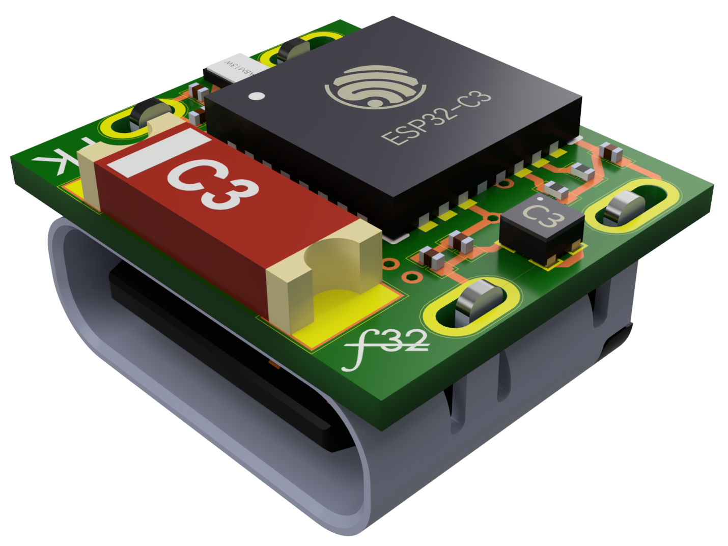
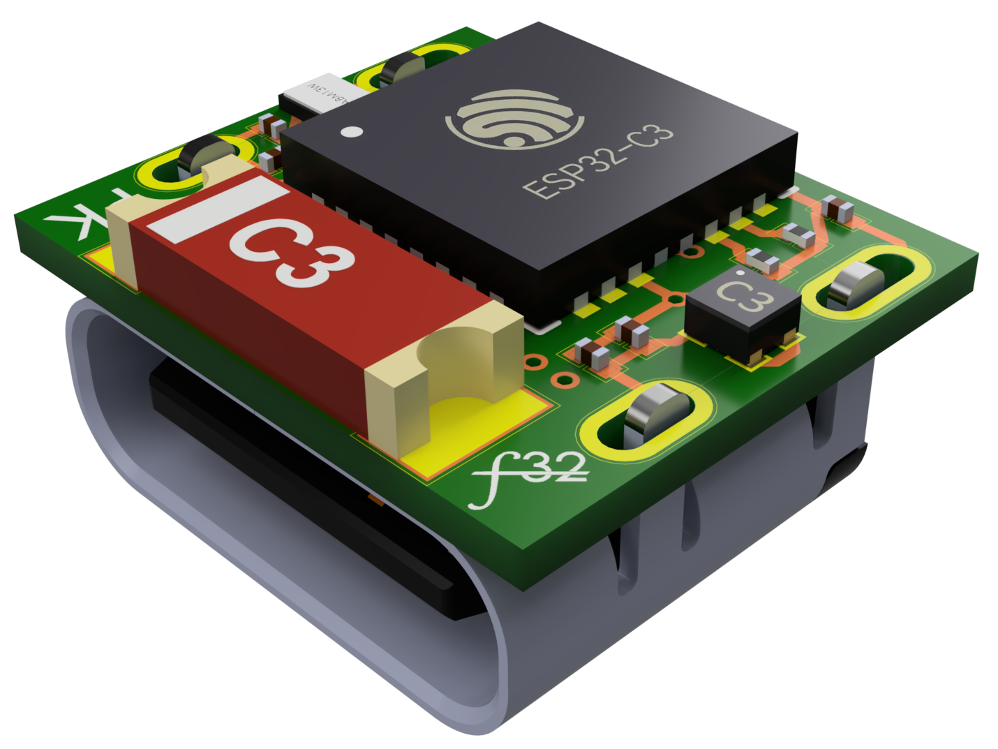
The f32 is an ultra-compact ESP32 development board designed to mount directly behind a USB-C receptacle. The PCB measures just 9.85 mm x 8.45 mm. It's powered by the ESP32-C3FH4 microcontroller and was created primarily for research and as a bit of a stress test for the ESP32, since it intentionally ignores many standard design guidelines. There's only one exposed GPIO and it is connected to an onboard LED, so most of the development on here would be more catered for wifi/web.
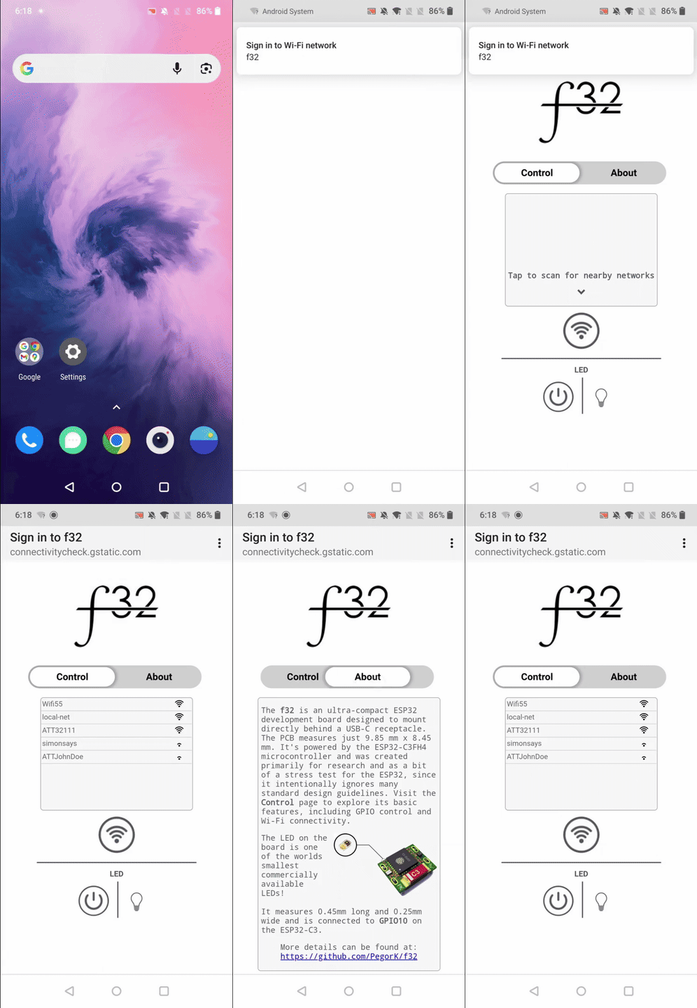
To test the f32 an example application was created that users can interact with. The application turns the f32 into a captive portal so when it's powered on it will show up as an open access point that the user can select from available WiFi networks. The user is then automatically sent to the f32's control page where they can interact with some of its basic functionality such as turning on an LED or scanning for surrounding WiFi networks. There's also an "About" page that provides a small overview of the device. Below are some screenshots and a gif of interacting with the device.
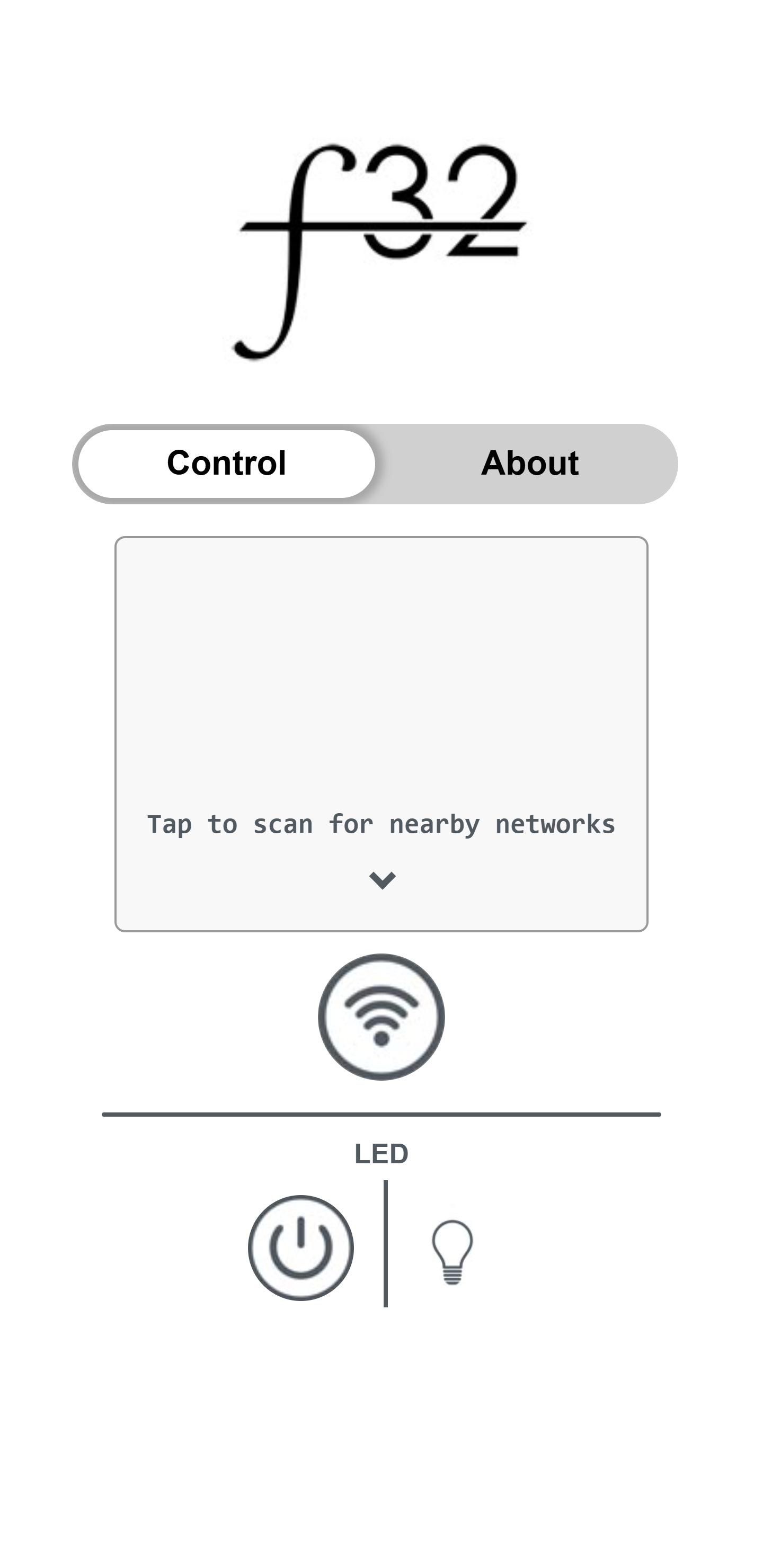
Main page of the captive portal. |
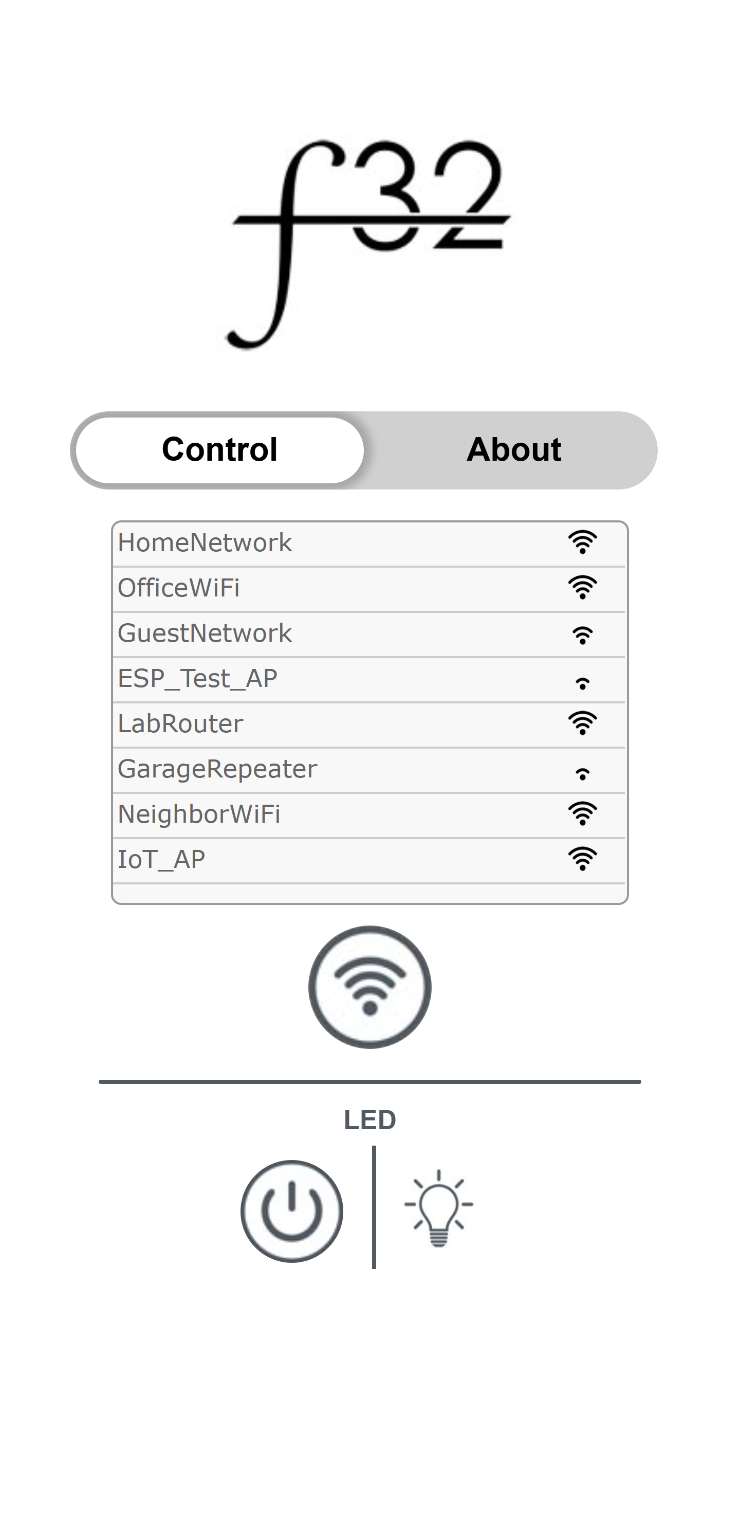
WiFi search and LED toggled on. |
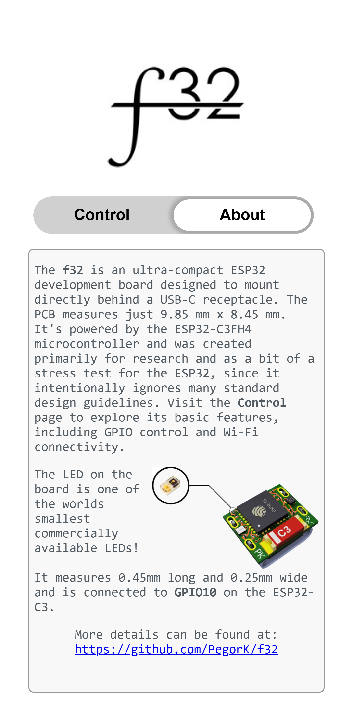
About page. |
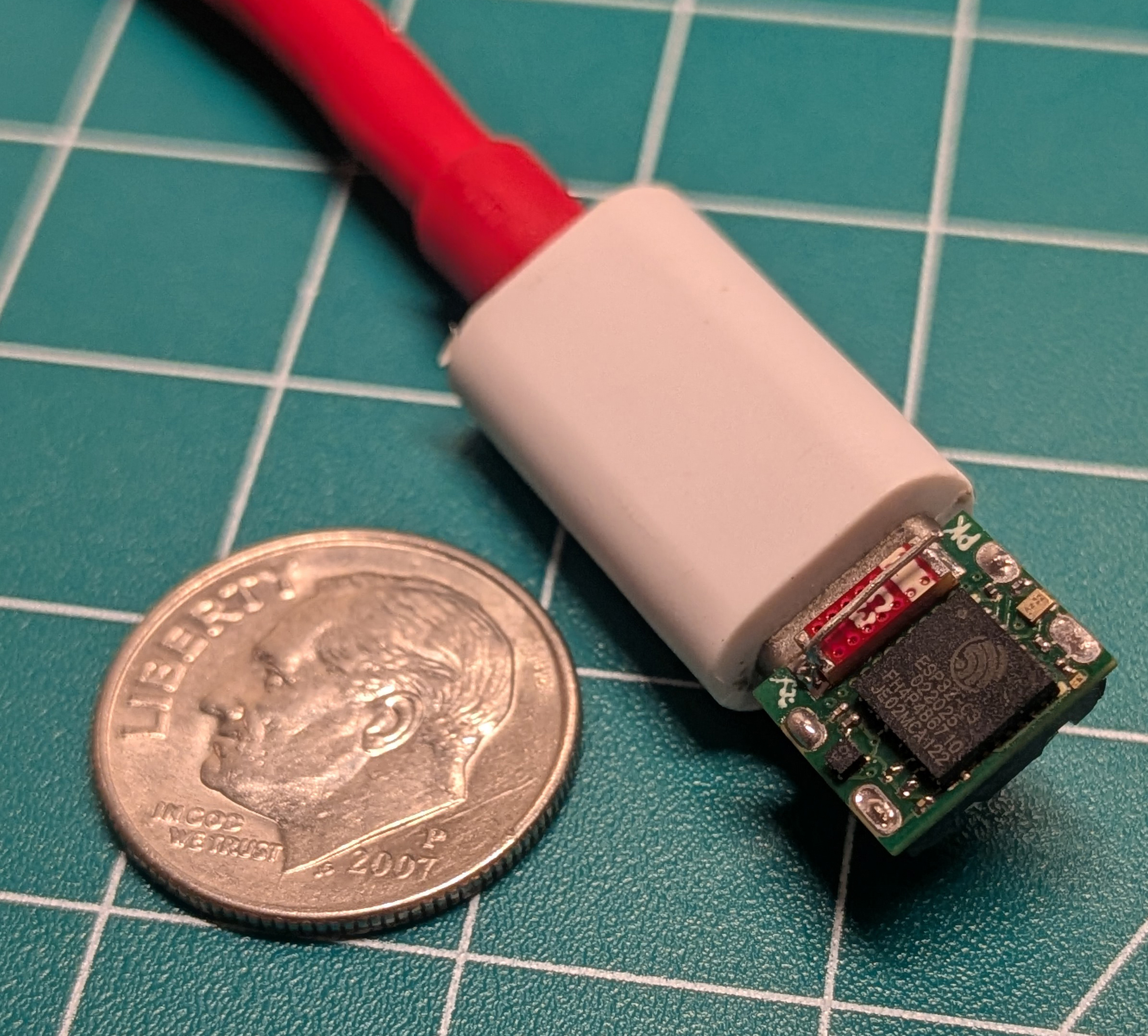
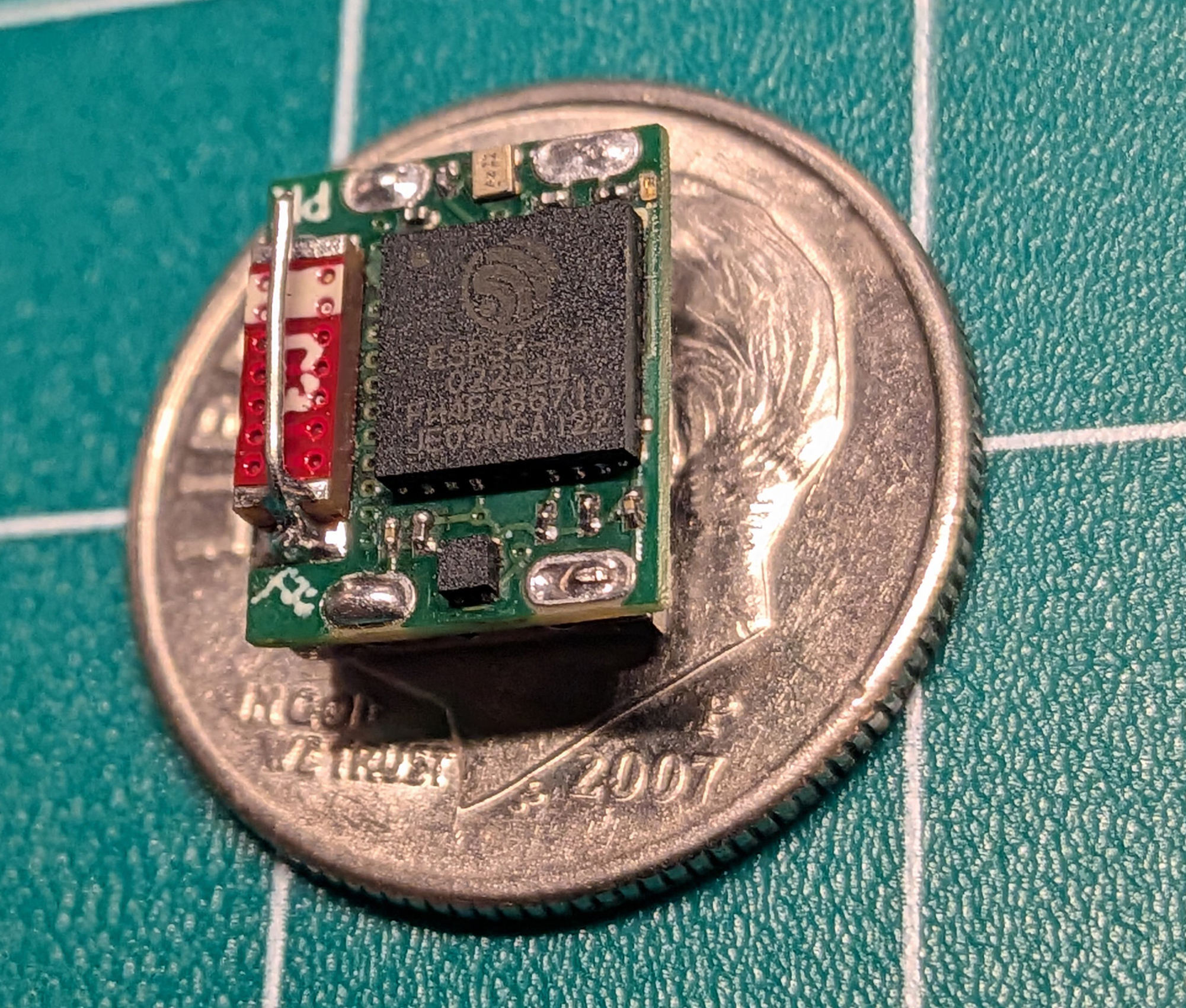
Initially the f32 didn't seem to want to work. I couldn't get it to connect to any networks or broadcast it's own network. Im 100% sure this is due to the poor antenna circuitry or lack of, but I did manage to get it functional after adding an additional tiny antenna onto the chip antenna as seen in the picture below. This was just a piece of bent wire soldered to the end lead and floating above the first lead.
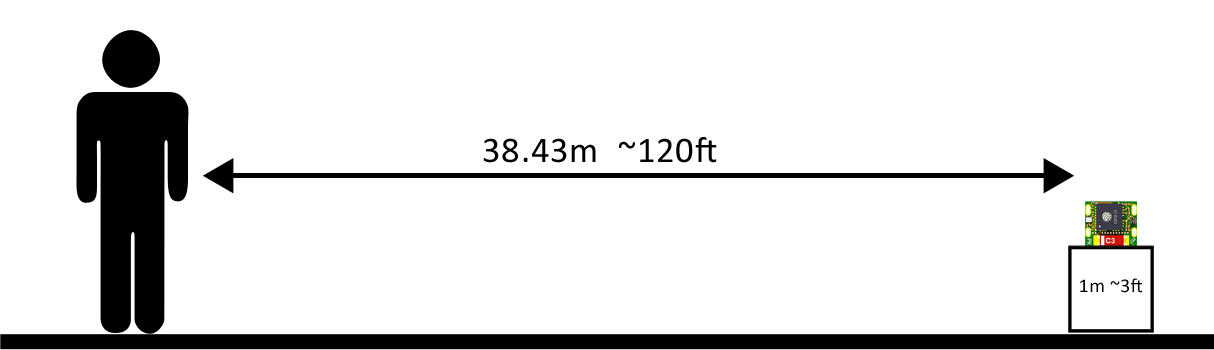
Since I don't have fancy signal testing equipment I relied on some manual testing such as seeing if I can still connect to the device and control the LED. In a clear line of sight test with the f32 placed about 3ft off the ground I was able to connect and perform scans/control the LED at roughly 120ft! This can be seen in my highly necessary depiction below.
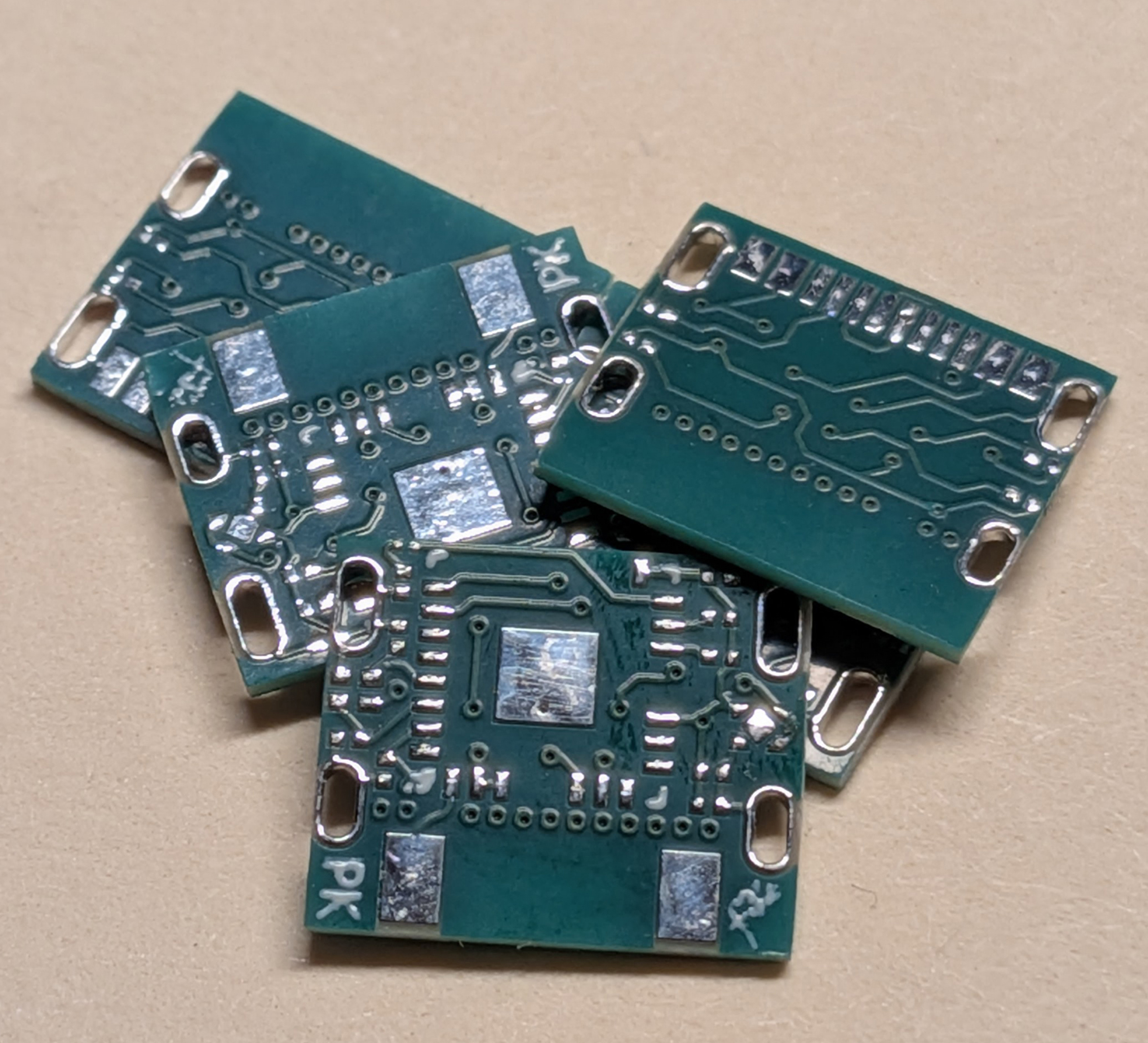
The PCB was designed using DipTrace and manufactured by PCBWay with a board thickness of 0.6mm, min hole size of 0.2mm, and min track/spacing of 4/4mil. At the time of making this it only cost $10.75 for 5 boards shipped! That still blows my mind. PCBWay does also offer assembly services, but I chose to assemble this at home and suffer a bit. This took a bit of trial and error with such small parts, but I decided the best way for me was to ditch the stencil and make flux my best friend.
Tools & parts used:
Steps to building one:
f32_gerber.zip found in the hardware folder to PCBWay with the specs mentioned above.f32_bom.pdf. These parts can be found on both DigiKey and Mouser except the antenna. I don't remember where I had originally ordered them, but I believe they are CrossAir CA-C03.
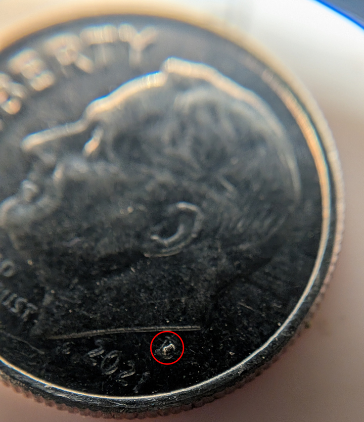
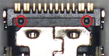
f32_reference.pdf.
After assembly you can use ESP-IDF VSCode extension or Arduino and upload whatever you'd like to the board or you can upload my example application using the steps below.
